Lightweight electromagnetic fan clutch

An electromagnetic fan and clutch technology, which is applied in the field of clutches, can solve the problems of complex structure of electromagnetic friction clutches, increased engine energy consumption, and high cost, and achieve the effects of light weight, reduced energy consumption, and reduced weight

Inactive Publication Date: 2018-08-31
苏州奥沃汽车配件有限公司
View PDF11 Cites 1 Cited by
  • Summary
  • Abstract
  • Description
  • Claims
  • Application Information

AI Technical Summary

Problems solved by technology

[0003] The electromagnetic fan clutch is composed of an electromagnetic friction clutch and an automatic temperature control switch. The structure of the electromagnetic friction clutch is relatively complicated, requiring multiple active friction plates and passive friction plates. The cost is high, the weight is heavy, and the energy consumption of the engine is increased. It needs to be improved.

Method used


Image

  • Lightweight electromagnetic fan clutch

Examples


Embodiment Construction

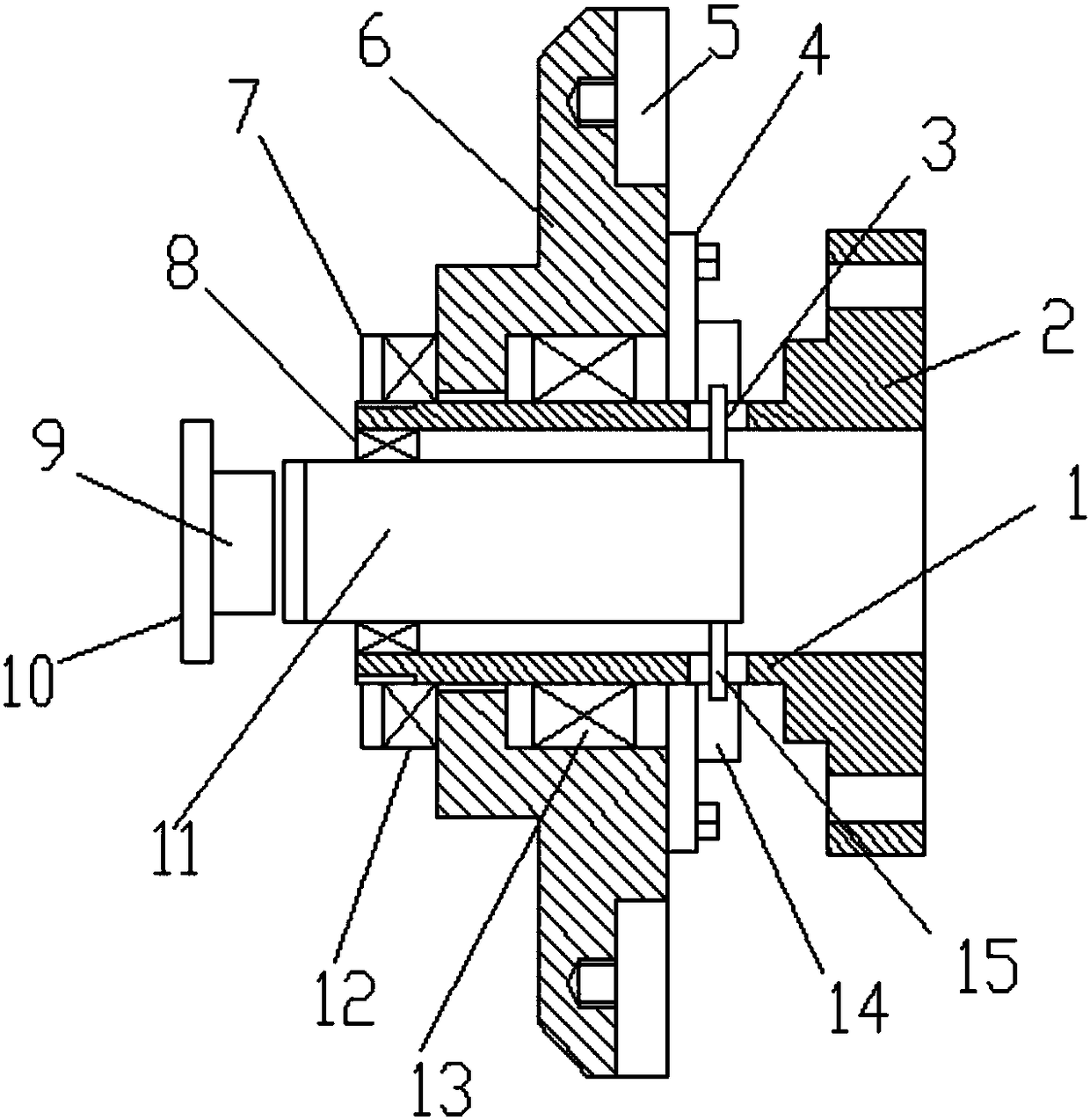
[0014] Combine below figure 1 And further illustrate the technical solution of the present invention through specific examples.

[0015] A lightweight electromagnetic fan clutch, comprising: a flange 2, a rotating sleeve 1, a fan blade fixed plate 6, an electromagnet 9 and a hollow cylinder 11, the flange 2 can be driven by an engine, and the rotating sleeve 1 is set on The front end of the flange 2 rotates with the flange 2, has a hollow structure and is light in weight, and can also be made of aluminum alloy to further reduce the weight.

[0016] The fan blade fixing plate 6 is arranged on the rotary sleeve 1, and the outer circle of the fan blade fixing plate 6 is provided with four fan blade installation grooves 5 in an annular array, which is convenient for fan blade installation.

[0017] A rolling bearing 13 is arranged in the inner hole of the blade fixing disk 6, and the rolling bearing 13 avoids the synchronous rotation of the blade fixing disk 6 and the rotating sl...


PUM


Abstract

The invention discloses a lightweight electromagnetic fan clutch. The lightweight electromagnetic fan clutch comprises a flange plate, a rotary sleeve, a fan blade fixing disc, an electromagnet and ahollow barrel. The fan blade fixing disc is arranged on the rotary sleeve, a rolling bearing is arranged in an inner hole of the fan blade fixing disc, a thrust bearing is arranged at the front end ofthe fan blade fixing disc, the electromagnet is arranged in front of the rotary sleeve, a first clutch piece is arranged at the rear end of the fan blade fixing disc, a second clutch piece located behind the first clutch piece is arranged on the rotary sleeve, sliding grooves are symmetrically formed in the outer circle of the rotary sleeve, the hollow barrel is concentrically arranged in the rotary sleeve, a supporting rod connected with the hollow barrel through the sliding grooves is arranged in an inner hole of the second clutch piece, and the front end of the hollow barrel stretches outof the rotary sleeve and is provided with an iron piece opposite to the electromagnet. According to the lightweight electromagnetic fan clutch, when the temperature of a water tank is high, engagementand disengagement actions are rapid, the dead weight is low, the requirement on driving force is low, and the energy consumption of an engine can be reduced.

Description

technical field [0001] The invention relates to the field of clutches, in particular to a lightweight electromagnetic fan clutch. Background technique [0002] The electromagnetic fan clutch usually uses the water temperature of the engine to automatically control the connection and disconnection of the electromagnetic clutch circuit, so that the fan speed changes and works according to the working conditions of the engine. [0003] The electromagnetic fan clutch is composed of an electromagnetic friction clutch and an automatic temperature control switch. The structure of the electromagnetic friction clutch is relatively complicated, requiring multiple active friction plates and passive friction plates. The cost is high, the weight is heavy, and the energy consumption of the engine is increased. It needs to be improved. . Contents of the invention [0004] The purpose of the present invention is to provide a lightweight electromagnetic fan clutch, which reduces its own w...

Claims


Application Information

Patent Timeline
Patent Type & Authority Applications(China)
IPC IPC(8): F16D27/02F16D27/14F01P7/08
CPCF01P7/084F16D27/02F16D27/14
Inventor 汤自知
Owner 苏州奥沃汽车配件有限公司
Why Eureka
Try Eureka