

ict
A tester and testing mechanism technology, applied in the field of ICT testers, can solve the problems of reverse insertion, single function of the top plate test, and inability to check whether the electrical components can be checked at the same time, so as to increase the detection efficiency and improve the detection ability.
- Summary
- Abstract
- Description
- Claims
- Application Information
AI Technical Summary
Problems solved by technology
Method used
Image

Examples
Embodiment 1
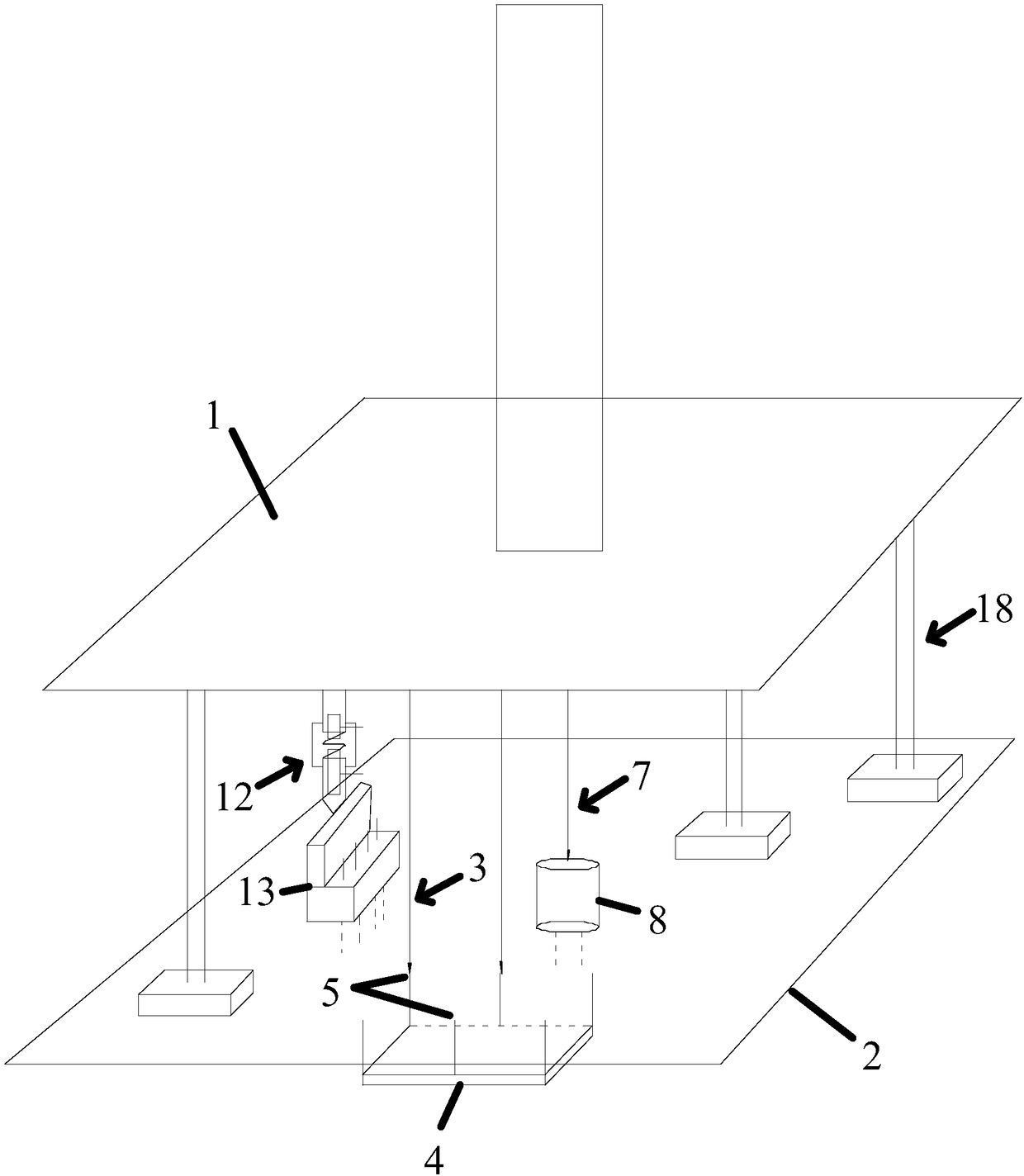
[0049] This embodiment provides an ICT tester, such as figure 1 shown, the ICT tester includes
[0050] The top plate 1 is driven by the cylinder to move towards the component surface of the circuit board 2;
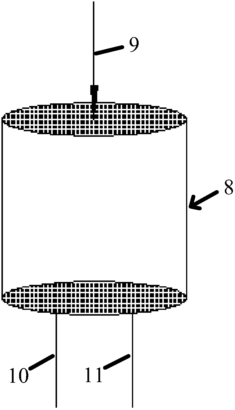
[0051] Electrical component pin testing agencies3 such as Image 6 As shown, it is arranged on the top plate 1, which includes the second probe 6 corresponding to the pin 5 of the electrical component 4 arranged on the component surface, and the second probe 6 is controlled by the The top plate 1 is driven and connected to the pin 5, and the top plate 1 is lowered during use. The second probe 6 is connected to the pin 5 on the surface of the component. It is judged by electrical signals that the pin 5 is located on the component. Whether the electrical components 4 on the surface can be used normally; solves the problem that it is impossible to test whether the electrical components are in normal use when the test points on the pin surface of the circuit board are blo...
Embodiment 2
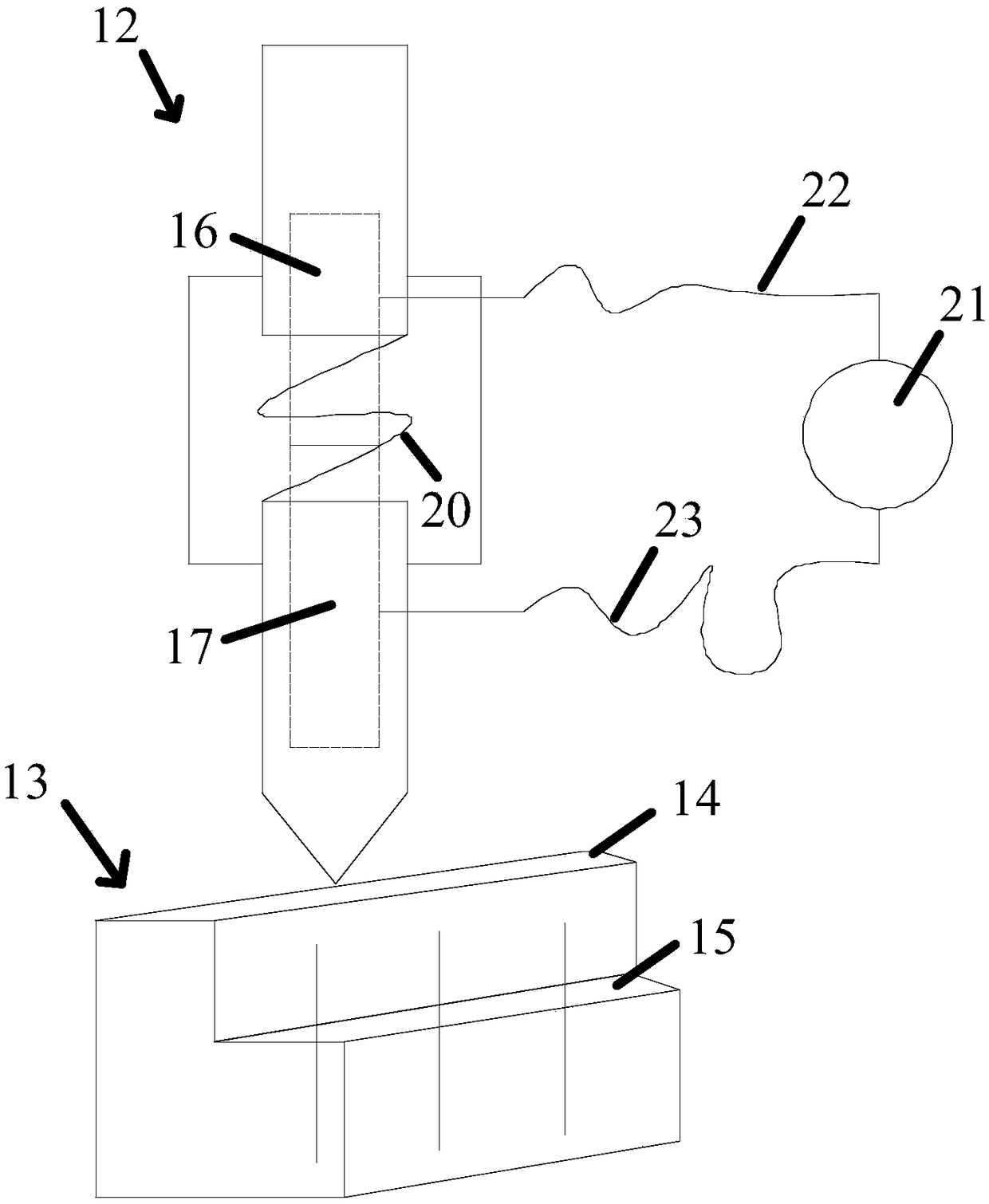
[0060]The difference between this embodiment and Embodiment 1 is that the first conductive member 16 and the second conductive member 17 are cylindrical structures, and a protective sleeve is sleeved on the side of the two away from each other, and the spring sleeve Placed on the outside of the columnar body and the two ends of the spring are fixedly connected to the ends of the protective sleeves sleeved on the first conductive member 16 and the second conductive member 17 respectively, and are respectively arranged on the first conductive member 16 and the second conductive member 17. 16 and the two protective sheaths on the second conductive member 17 are also provided with an outer protective sheath for covering the connecting part of the first conductive member 16 and the second conductive member 17 . The above-mentioned protective cover and outer protective cover are used to prevent other parts from touching the connection position of the first conductive member and the s...
PUM
 Abstract
Description
Claims
Application Information