
Water-cooling circulation dedusting computer mainframe case structure

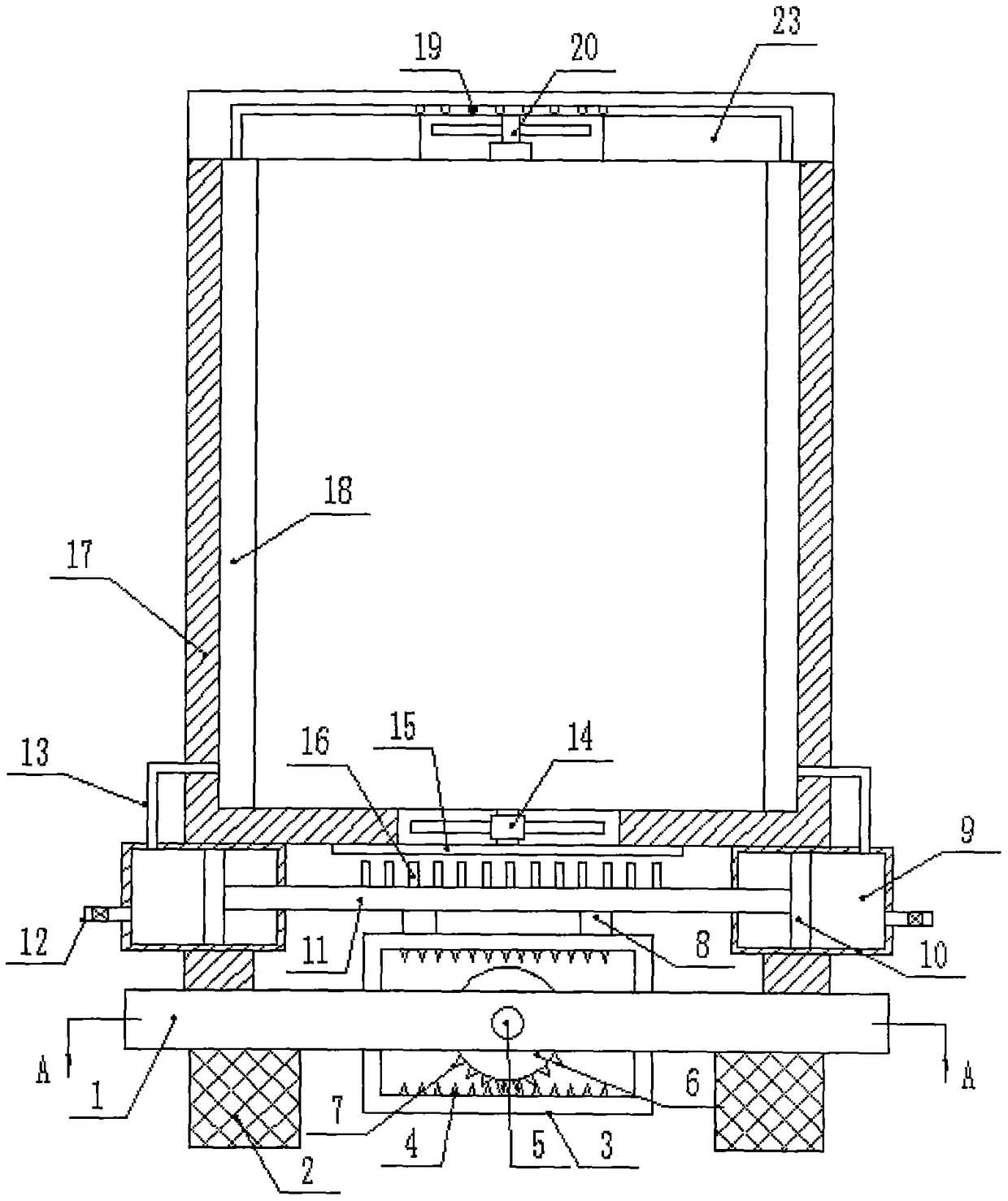
A water-cooling cycle and computer technology, applied in computing, instruments, electrical digital data processing, etc., can solve the problems of hot and cold air exchange, large heat generation, accumulation, etc., to ensure normal operation, increase heat dissipation performance, and avoid accumulation effects

Inactive Publication Date: 2018-08-31
QINGDAO HUANGHAI UNIV
View PDF4 Cites 33 Cited by
  • Summary
  • Abstract
  • Description
  • Claims
  • Application Information

AI Technical Summary

Problems solved by technology

[0003] The mainframe of the computer generates a lot of heat during use, and real-time heat dissipation and cooling processing is required. The heat dissipation effect of the current computer mainframe chassis is not ideal, and most of them dissipate heat through separate cooling. This cooling method may lead to a large amount of heat. Accumulated inside the mainframe case, it seriously affects the working life of the entire computer mainframe. At the same time, in order to ensure the heat dissipation effect of the CPU, memory, hard disk, optical drive and other components inside the mainframe, we will install these components near the main case shell. The air vent and the corresponding dust filter will cause a large amount of dust to accumulate near the dust filter. If it is not cleaned in time, the air vent will not be able to exchange hot and cold air, which will affect the performance and practicability of the entire computer host. Not strong

Method used


Image

  • Water-cooling circulation dedusting computer mainframe case structure
  • Water-cooling circulation dedusting computer mainframe case structure
  • Water-cooling circulation dedusting computer mainframe case structure

Examples


Embodiment Construction

[0021] It should be noted that, in the case of no conflict, the embodiments of the present invention and the features in the embodiments can be combined with each other.

[0022] In describing the present invention, it should be understood that the terms "center", "longitudinal", "transverse", "upper", "lower", "front", "rear", "left", "right", " The orientations or positional relationships indicated by "vertical", "horizontal", "top", "bottom", "inner" and "outer" are based on the orientations or positional relationships shown in the drawings, and are only for the convenience of describing the present invention and Simplified descriptions, rather than indicating or implying that the device or element referred to must have a particular orientation, be constructed and operate in a particular orientation, and thus should not be construed as limiting the invention. In addition, the terms "first", "second", etc. are used for descriptive purposes only, and should not be understood ...


PUM


Abstract

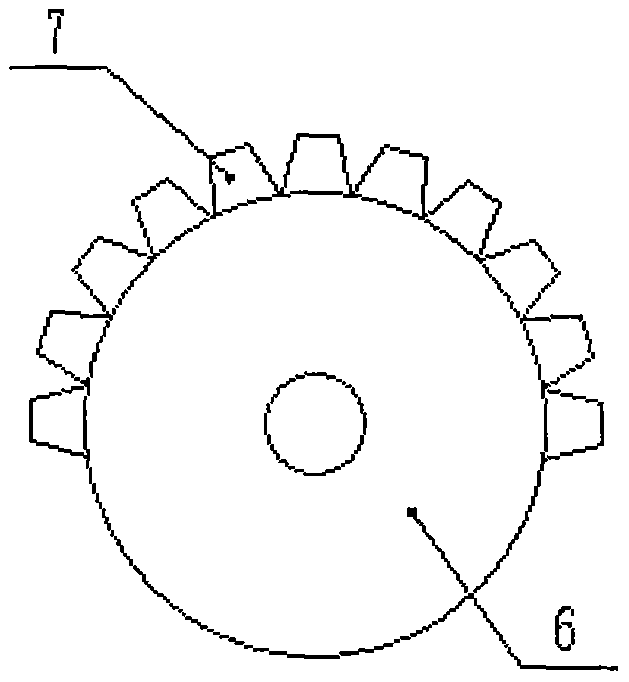
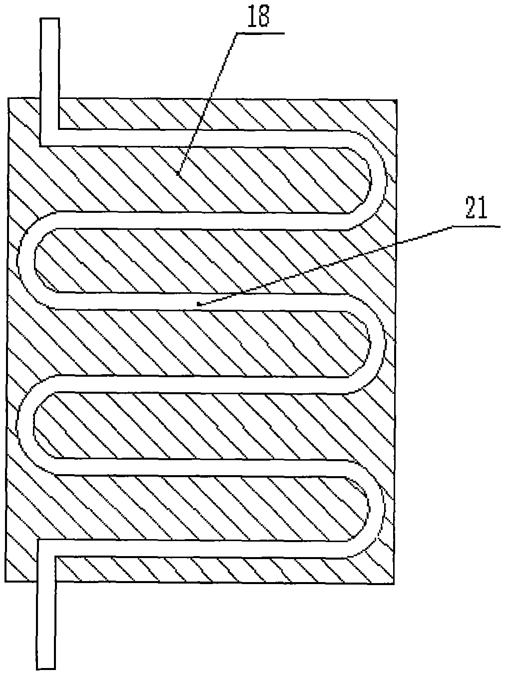
The invention discloses a water-cooling circulation dedusting computer mainframe case structure. The structure comprises a supporting base, wherein a meshing slot is arranged in the middle of the supporting base, a driving shaft is installed inside the meshing slot, a driving gear is installed in the middle of the driving shaft, a rack frame is arranged at the outer side of the driving gear in a meshing mode, fixed pillars are connected to the upper end of the rack frame, circulating water tanks are installed at the two sides of the upper end of the supporting base, a water diversion piston isarranged inside each circulating water tank, a guide rod is connected between the water diversion pistons, a mainframe case is arranged at the upper ends of the circulating water tanks, an air-in fanis arranged at the lower end of the mainframe case, a dust filtering net is installed at the lower end of the air-in fan, heat absorption plates are arranged at the two ends of the inner wall of themainframe case, a top plate is installed at the upper end of the mainframe case, a wire net is arranged in the middle of the top plate, and a cooling elbow is installed at the upper end of the wire net. Through the structure, the water-diversion heat dissipation effect of the circulating water tanks is achieved, meanwhile, dust brushes continuously clear dust on the dust filtering net, piling of dust is avoided, and the heat dissipation performance of the whole mainframe case is enhanced.

Description

technical field [0001] The invention relates to the technical field of computer mainframe chassis structure, in particular to a water-cooled circulating dust removal type computer mainframe chassis structure. Background technique [0002] Computer, commonly known as computer, is one of the most advanced scientific and technological inventions in the 20th century. It has had an extremely important impact on human production and social activities and has developed rapidly with strong vitality. Its application fields have expanded from the initial military scientific research application to society. In various fields, a large-scale computer industry has been formed, which has led to technological progress on a global scale, which has triggered profound social changes. Computers have spread throughout general schools, enterprises and institutions. The host computer refers to the main body part of the computer except the input and output devices, and it is also the control box us...

Claims


Application Information

Patent Timeline
IPC IPC(8): G06F1/18G06F1/20B08B1/00
CPCG06F1/181G06F1/20B08B1/12B08B1/30
Inventor 孙守强崔宪平苏玉梅李宗锋刘燕
Owner QINGDAO HUANGHAI UNIV
Features
  • Generate Ideas
  • Intellectual Property
  • Life Sciences
  • Materials
  • Tech Scout
  • Unparalleled Data Quality
  • Higher Quality Content
  • 60% Fewer Hallucinations
Learn More