Check patentability & draft patents in minutes with Patsnap Eureka AI!

Self-recovery overvoltage-and-undervoltage protection device and circuit thereof

A protector circuit, overvoltage and undervoltage technology, applied in emergency protection circuit devices, protection against overvoltage, protection against undervoltage or no voltage, etc., to achieve the effect of improving detection accuracy

Pending Publication Date: 2018-08-31
长城电器集团浙江科技有限公司
View PDF0 Cites 3 Cited by
  • Summary
  • Abstract
  • Description
  • Claims
  • Application Information

AI Technical Summary

Problems solved by technology

[0003] The invention provides a self-recovery overvoltage and undervoltage protector and its circuit to solve the problems existing in the existing self-recovery overvoltage and undervoltage protection appliances

Method used


Image

  • Self-recovery overvoltage-and-undervoltage protection device and circuit thereof
  • Self-recovery overvoltage-and-undervoltage protection device and circuit thereof
  • Self-recovery overvoltage-and-undervoltage protection device and circuit thereof

Examples


Embodiment 1

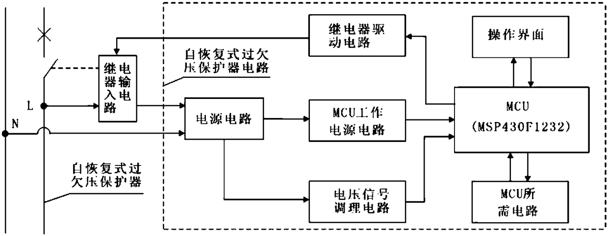
[0024] Such as image 3 As shown, a self-resetting overvoltage and undervoltage protector circuit, the circuit includes a power supply circuit, a voltage signal conditioning circuit, an MCU working power supply circuit, a microcontroller MCU, a relay drive circuit, a circuit required by the microcontroller MCU, and an operation interface circuit and relay input circuit;

[0025] The circuit required by the microcontroller MCU, the MCU working power supply circuit, the relay drive circuit, and the voltage signal conditioning circuit are respectively electrically connected to the microcontroller MCU;

[0026] The MCU working power supply circuit and the voltage signal conditioning circuit are respectively electrically connected to the power supply circuit;

[0027] The relay input circuit is electrically connected to the power supply circuit and the relay drive circuit respectively;

[0028] The voltage signal conditioning circuit uses a rectifier diode D6 to form a half-wave ...

Embodiment 2

[0034] Such as figure 2 As shown, a self-resetting overvoltage and undervoltage protector, the protector is installed with a self-resetting overvoltage and undervoltage protector circuit according to any one of claims 1-3.

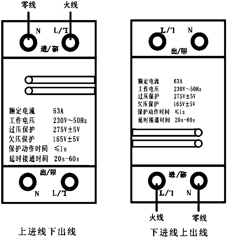
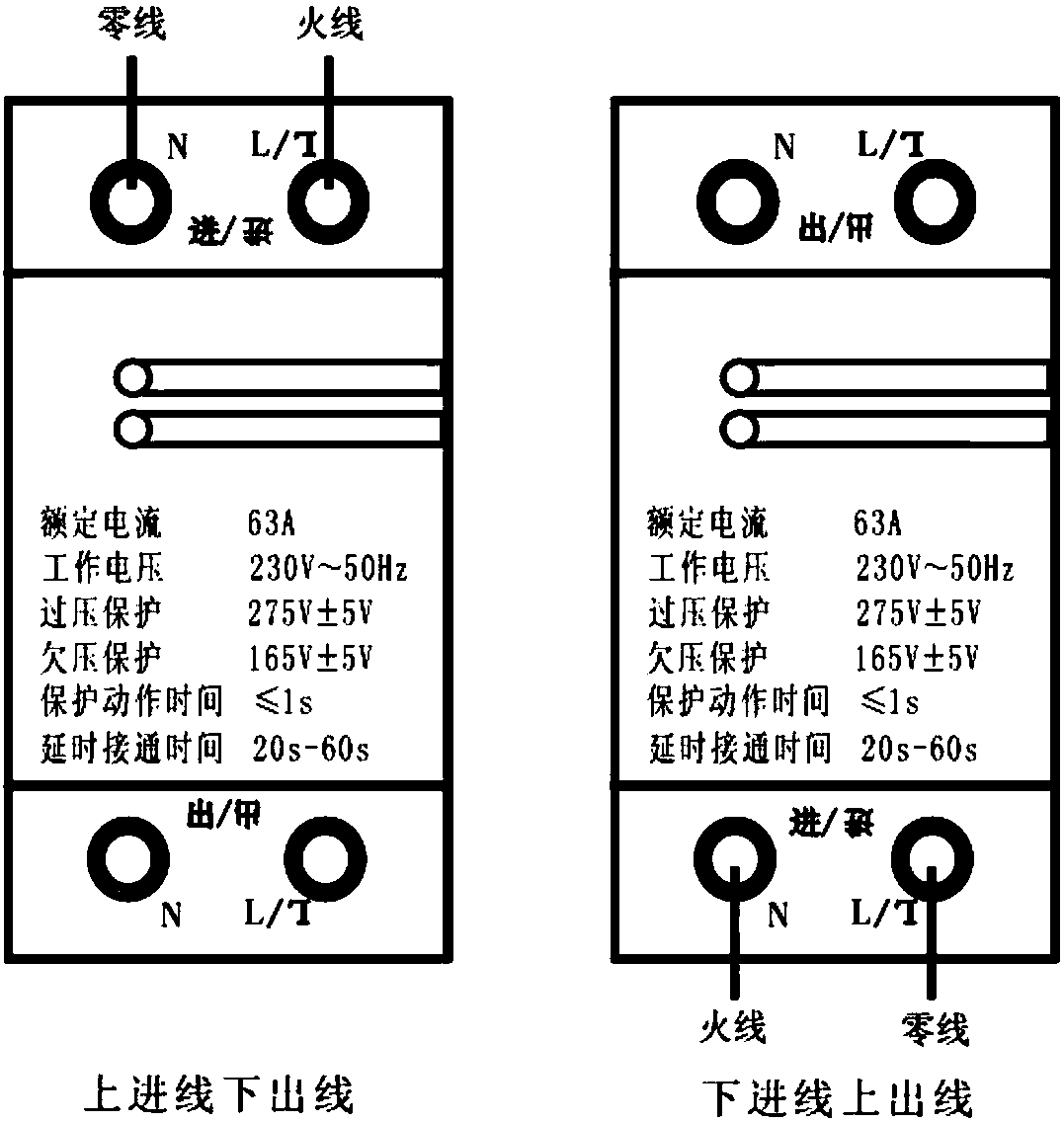
[0035] As a major improvement of the technical solution of this embodiment, the resistor R2 is installed while the resistor R3 is not installed when "upper incoming line and lower outgoing line"; the resistor R2 is not installed when the "bottom incoming line is outgoing", and the resistor R3 is installed.

[0036] As a great improvement of the technical solution of this embodiment, switch 1 is turned on and switch 2 is turned off when "upper incoming line and lower outgoing line";

[0037] In order to solve the problem that the traditional self-recovery overvoltage and undervoltage protector cannot realize the installation of "upper incoming line and lower outgoing line" and "bottom incoming line and outgoing line", the product does not turn around, and ...


PUM


Abstract

The invention relates to the technical field of self-recovery overvoltage-and-undervoltage protection electric appliances, in particular to a self-recovery overvoltage-and-undervoltage protection device and a circuit thereof. The circuit comprises a power circuit, a voltage signal conditioning circuit, an MCU working power circuit, a micro control unit (MCU), a relay drive circuit, an MCU requiredcircuit, an operation interface circuit and a relay input circuit. According to the self-recovery overvoltage-and-undervoltage protection device and the circuit thereof, the relay input circuit and the relay drive circuit are cooperatively used, it can be conveniently and effectively achieved that a product does not need to be turned during 'upper line inlet and lower line outlet' and 'lower lineinlet and upper line outlet' installation, and meanwhile a null line and a live line are located at the same position. Meanwhile, the self-recovery overvoltage-and-undervoltage protection device circuit adopts the simple, convenient and effective half-wave-rectification and resistor-voltage-dropping voltage signal conditioning circuit for improving the detection accuracy of voltage signals, and the problem that as an operational amplifier is used as a core for composing a hysteresis comparator in a traditional mode, the consistency of overvoltage-and-undervoltage recovery values is poor is effectively solved.

Description

technical field [0001] The invention relates to the technical field of self-recovery overvoltage and undervoltage protection appliances, in particular to a self-resetting overvoltage and undervoltage protector and a circuit thereof. Background technique [0002] The installation method of the self-recovery overvoltage and undervoltage protection device is divided into two installation methods: "upper incoming line and lower outgoing line" or "bottom incoming line and outgoing line". However, when the traditional self-recovery overvoltage and undervoltage protectors are installed in order to realize the installation method of "upper incoming line and lower outgoing line" or "bottom incoming line and outgoing line", the product needs to be reversed and installed, such as figure 1 shown. In the installation of "upper incoming line and lower outgoing line", the zero line of the product is on the left, and the live line is on the right; in the installation of "bottom incoming li...

Claims


Application Information

Patent Timeline
IPC IPC(8): H02H3/20H02H3/24H02H3/253H02H1/00
CPCH02H1/0007H02H3/207H02H3/24H02H3/253
Inventor 余存泰章火明李其利
Owner 长城电器集团浙江科技有限公司
Features
  • R&D
  • Intellectual Property
  • Life Sciences
  • Materials
  • Tech Scout
  • Unparalleled Data Quality
  • Higher Quality Content
  • 60% Fewer Hallucinations
Learn More