
Ferromagnetic-coupling vibration energy collection device with double cantilever beams

A vibration energy harvesting, double cantilever beam technology, applied in piezoelectric effect/electrostrictive or magnetostrictive motors, generators/motors, electrical components, etc. and other problems, to achieve the effect of improving energy collection efficiency and bandwidth, simple structure setting and design, easy production and maintenance

Inactive Publication Date: 2018-08-31
TIANJIN UNIV
View PDF2 Cites 11 Cited by
  • Summary
  • Abstract
  • Description
  • Claims
  • Application Information

AI Technical Summary

Problems solved by technology

However, the frequency band of the traditional cantilever beam piezoelectric energy harvesting device is very narrow, which directly limits the conversion efficiency of the collector. These problems limit the application of piezoelectric vibration energy harvesting technology.
A more common solution is to use an array structure and use multiple cantilever beams to obtain multiple resonance frequencies. However, the resonance frequencies of this method are still discrete, and it is difficult to obtain high energy conversion efficiency, which is not very practical.

Method used


Image

  • Ferromagnetic-coupling vibration energy collection device with double cantilever beams
  • Ferromagnetic-coupling vibration energy collection device with double cantilever beams
  • Ferromagnetic-coupling vibration energy collection device with double cantilever beams

Examples


Embodiment Construction

[0022] Embodiments of the present invention are described below through specific examples, and those skilled in the art can easily understand other advantages and functions of the present invention from the content disclosed in this specification. The present invention can also be implemented or applied through other different specific implementation modes, and various modifications or changes can be made to the details in this specification based on different viewpoints and applications without departing from the spirit of the present invention. It should be noted that, in the case of no conflict, the following embodiments and features in the embodiments can be combined with each other.

[0023] It should be noted that the diagrams provided in the following embodiments are only schematically illustrating the basic ideas of the present invention, and only the components related to the present invention are shown in the diagrams rather than the number, shape and shape of the com...


PUM


Abstract

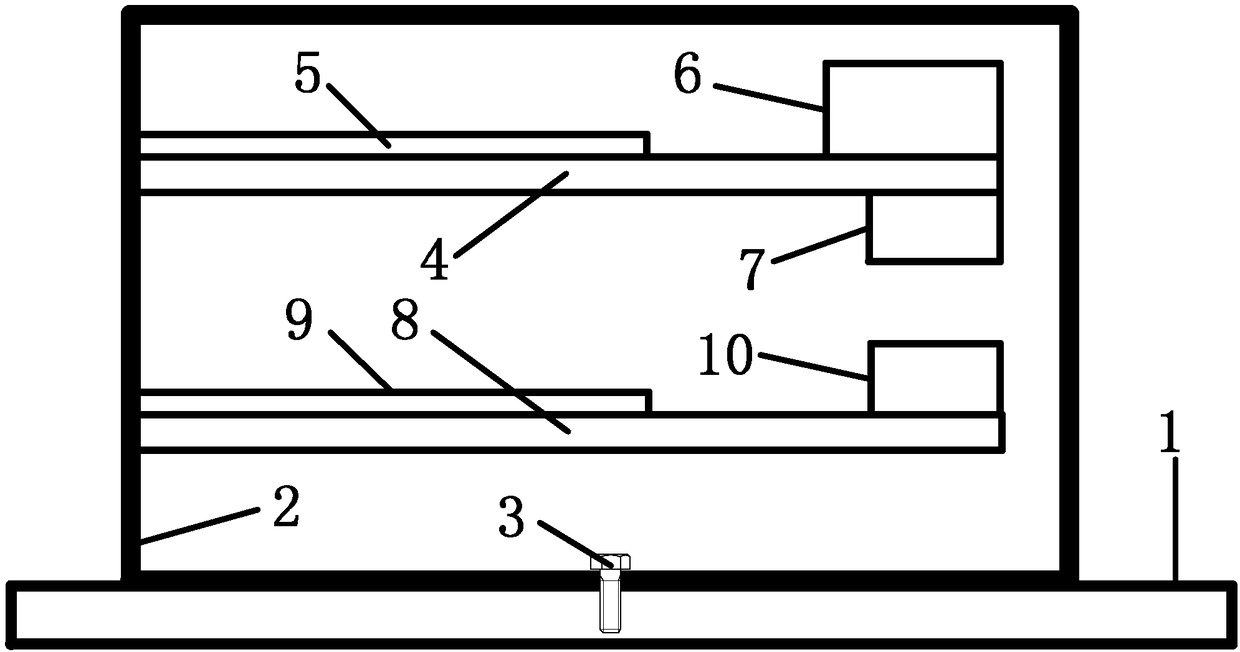
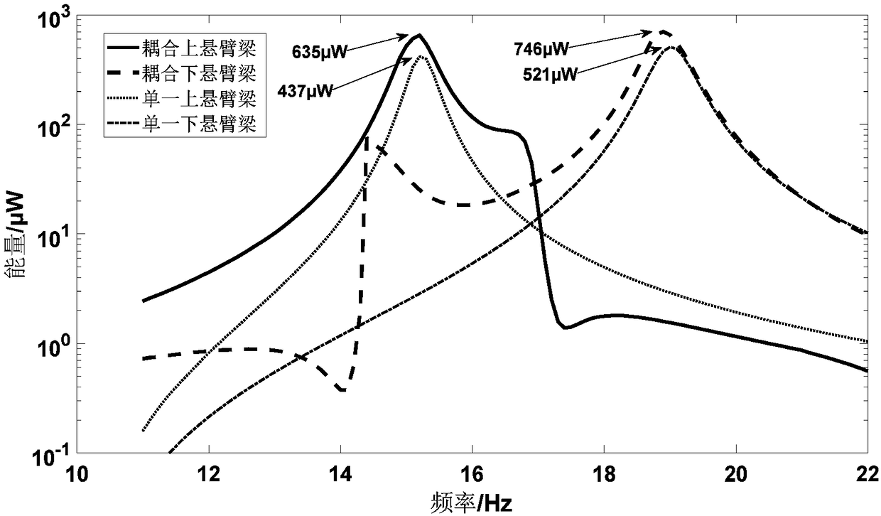
The invention relates to a ferromagnetic-coupling vibration energy collection device with double cantilever beams. The structure of the ferromagnetic-coupling vibration energy collection device comprises a vibration structure, an external framework, a fastening piece, an upper cantilever beam, an upper piezoelectric material block, a mass block, an upper cantilever beam ferromagnetic block, a lower cantilever beam, a lower piezoelectric material block and a lower cantilever beam ferromagnetic block. The ferromagnetic-coupling vibration energy collection device has the effect that the double cantilever beams are used as a basic energy collection structure; compared with the other methods, the structure is simple to arrange and design and is easy to fabricate and maintain; the two cantileverbeams are arranged to collect energy, the resonant frequencies of the two cantilever beams can be different by attaching the mass block onto the upper cantilever beam, so that the beneficial effect of multi-resonant frequency bands is achieved; a non-linear force is introduced by ferromagnetic coupling; and compared with the same-size cantilever beam without ferromagnet, the ferromagnetic-coupling vibration energy collection device has the advantages that the energy collection efficiency is greatly improved, the bandwidth is greatly expanded, the broadening frequencies of the two cantilever beams can be coincided, so that the output is improved to be applicable to a more complicated working condition.

Description

technical field [0001] The invention belongs to the technical field of energy conversion and collection, in particular to a magnet-coupled double cantilever beam vibration energy collection device. Background technique [0002] In order to realize information collection and human-computer interaction, miniaturized computing devices are usually integrated into everyday objects to form the Internet of Things. The wireless sensor network plays a key role. Compared with the traditional sensor technology, this technology has the characteristics of no wiring and free networking. However, the power supply problem of wireless sensors has not been fundamentally resolved. With the continuous decline of power consumption, it is feasible to use the energy in the environment to supply energy to wireless sensors. [0003] There are a lot of various types of mechanical energy in our living environment, such as wind motion, body movement, muscle stretching, sound waves, ultrasonic waves, n...

Claims


Application Information

Patent Timeline
Patent Type & Authority Applications(China)
IPC IPC(8): H02N2/18
CPCH02N2/186
Inventor 芮小博李一博曾周末刘悦郑晓雷封皓黄新敬
Owner TIANJIN UNIV
Learn More