Wear-resistant element for a comminuting device

A crushing device and component technology, applied in the field of wear-resistant components, can solve problems such as high maintenance costs and long downtime

Active Publication Date: 2018-08-31
F L SMIDTH & CO AS
View PDF9 Cites 2 Cited by
  • Summary
  • Abstract
  • Description
  • Claims
  • Application Information

AI Technical Summary

Problems solved by technology

Replacing wear-resistant elements leads to long downtimes and high maintenance costs of e.g. roller mills

Method used


Image

  • Wear-resistant element for a comminuting device
  • Wear-resistant element for a comminuting device
  • Wear-resistant element for a comminuting device

Examples


Embodiment Construction

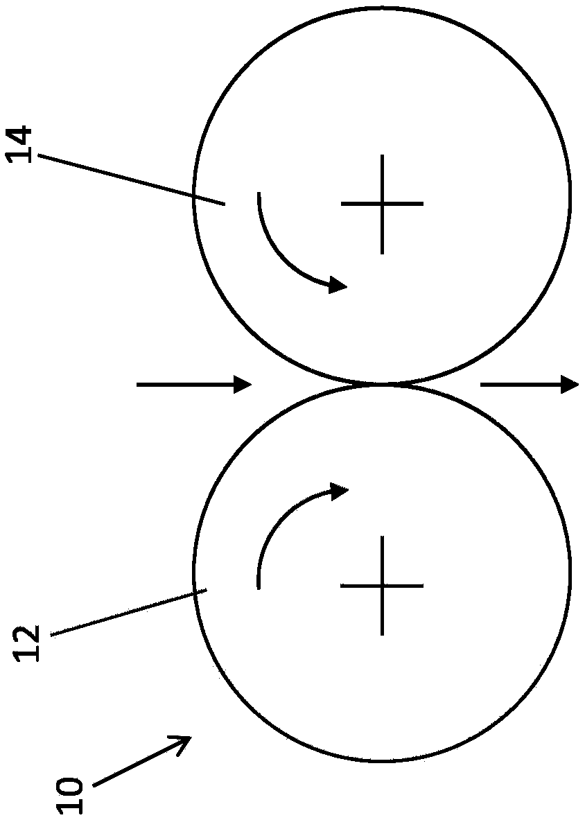
[0025] figure 1 A comminution device 10 is schematically shown, in particular a roller mill. The comminuting device 10 comprises two grinding rollers (shown schematically as circular) having wearing surfaces 12, 14, which have the same diameter and are arranged alongside each other. Between the wear surfaces 12 , 14 of the grinding rollers a grinding gap is formed, the size of which can be set, for example.

[0026] During operation of the comminuting device 10, the grinding rollers rotate in opposite directions to each other in the direction of rotation indicated by the arrows, wherein the material passes through the grinding gap in the falling direction and is ground.

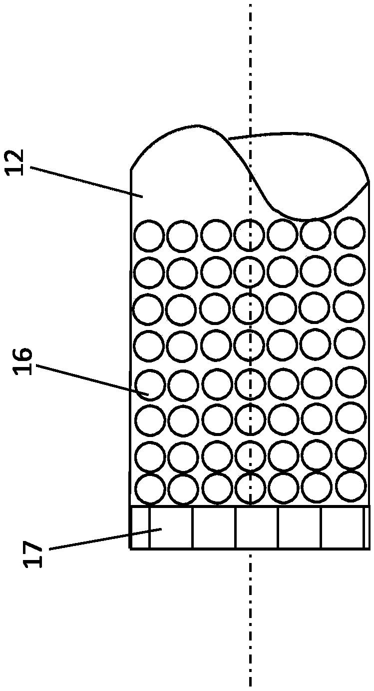
[0027] figure 2 The end region of a grinding roll is shown with a wear surface 12 on which wear-resistant elements 16 are mounted. Wear-resistant elements 16 are mounted on the outer circumference of the grinding roller surface. For example, in figure 2 The spaced-apart wear elements 16 arranged next t...


PUM


Abstract

The invention relates to a wear-resistant element (16c) for partial insertion into a recess on a surface of a wear area of a comminuting device, the wear-resistant element (16c) comprising a fasteningsection (24) which can be connected to the recess on the surface of the wear area and has a wear portion (22) that protrudes at least in part from the surface of the wear area. According to the invention, the fastening section (24) comprises a material that has a lower wear resistance than the material of the wear portion (22), the wear portion (22) extends beyond the fastening section (24) in the vertical direction of the wear-resistant element (16c), and the fastening section (24) is in the form of a sleeve.

Description

technical field [0001] The invention relates to a wear-resistant element for being partially inserted into a recess of a wear surface of a comminution device, and a comminution device having such a wear-resistant element. Background technique [0002] In comminution devices, such as grinding rolls, in particular for bed comminution of materials such as hard ore, a high level of wear of the wear surfaces, such as grinding roll surfaces, occurs during operation of the comminution device. In order to counteract this wear, it is known, for example, from DE 2006010 042 A1 to mount additional wear-resistant elements on the surface of the grinding roller. At certain degrees of wear, the wear-resistant elements of the grinding rollers must be replaced to ensure efficient grinding. Replacing the wear elements leads to long downtimes and high maintenance costs of eg roller mills. Contents of the invention [0003] It is therefore an object of the present invention to provide a wea...

Claims


Application Information

Patent Timeline
Patent Type & Authority Applications(China)
IPC IPC(8): B02C4/30
CPCB02C4/305B02C2210/02
Inventor 巴里斯·厄尔马克英戈·内特梅尔马塞尔·班内特
Owner F L SMIDTH & CO AS
Why Eureka
Try Eureka