Method for producing a base body of a turbine blade

A technology of moving blades and bases, which is applied in the direction of blade support components, engine functions, engine components, etc., and can solve problems such as resonance frequency excitation frequency deviation

Active Publication Date: 2018-08-31
SIEMENS ENERGY GLOBAL GMBH & CO KG
View PDF6 Cites 0 Cited by
  • Summary
  • Abstract
  • Description
  • Claims
  • Application Information

AI Technical Summary

Problems solved by technology

Therefore, in the prior art, the turbine rotor blades are designed such that the resonant frequency of the turbine rotor blades is offset relative to the excitation frequency of the stationary gas turbine

Method used


Image

  • Method for producing a base body of a turbine blade
  • Method for producing a base body of a turbine blade
  • Method for producing a base body of a turbine blade

Examples


Embodiment Construction

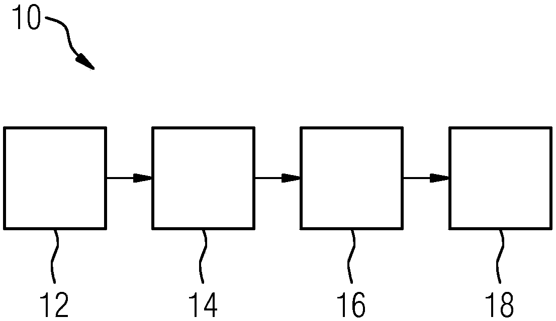
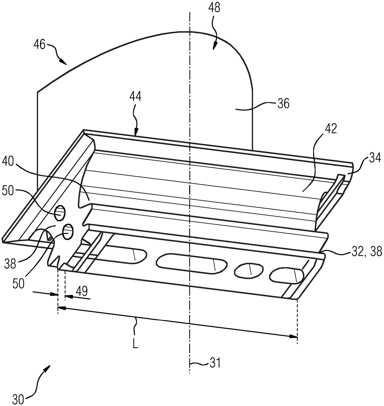
[0022] figure 1 A method 10 according to the invention is shown. Base body 30 (for making turbine rotor buckets) image 3 ) method 10 includes providing, in a first step 12 , a base body 30 of a turbine rotor bucket. The base body 30 includes, in sequence, a bucket root 32 , a platform 34 and a bucket airfoil 36 along a virtual longitudinal axis 31 .

[0023] The bucket root 32 has a fir-tree profile when viewed perpendicular to the planar end face 38 of the bucket root 32 and merges into the underside 42 of the platform 34 via a so-called bucket neck 40 . The platform includes a hot gas side 44 opposite the bottom side 42 to which the bucket airfoil 36 is monolithically connected. The bucket airfoil 36 is formed in the shape of a drop and is aerodynamically curved to form a pressure side 46 and a suction side 48 .

[0024] The bucket root 32 extends over a length L between two planar end faces 38 arranged axially opposite each other.

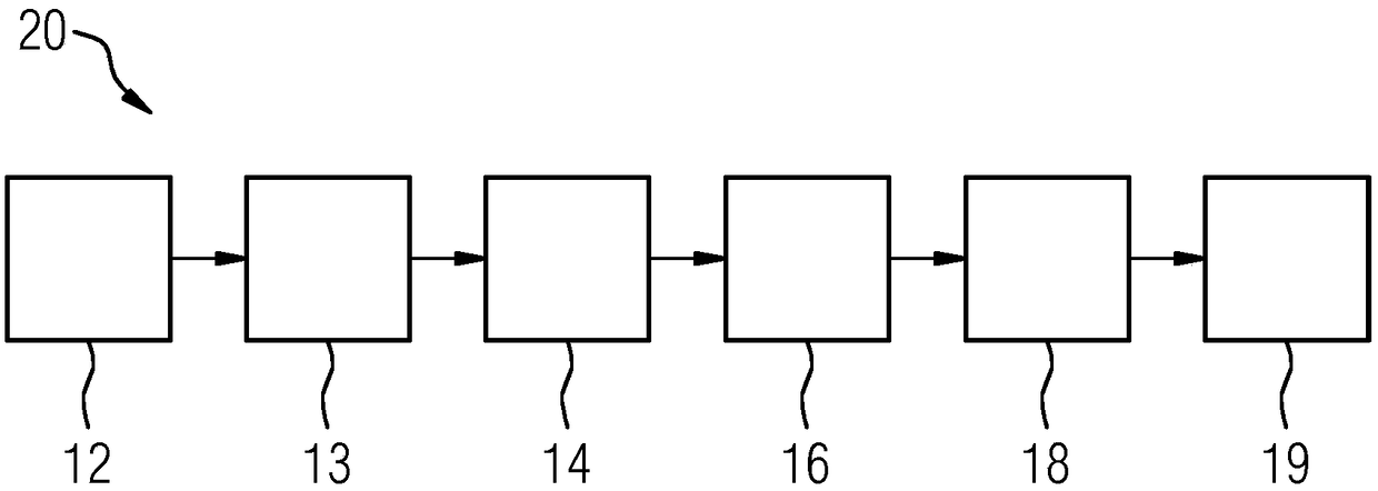
[0025] In the second manufacturing ...


PUM


Abstract

The invention relates to a method for producing turbine rotor blades or the base bodies (30) thereof, the frequency property of which can be adapted particularly easily to the required boundary conditions. To this end, recesses (50) are introduced into the blade root (32) and / or by reducing a dimension below the corresponding target value if the base body has (30) insufficient vibrational properties. In this way, a method is disclosed in which the vibrational property of the turbine rotor blades can be set in a particularly easy and variable manner. As a result, the reject rate in the production of turbine rotor blades can be reduced.

Description

technical field [0001] The present invention relates to a method for manufacturing a base body of a turbine rotor bucket comprising at least the following successive steps: providing a base body comprising, in sequence along a virtual longitudinal axis, a bucket root, a bucket platform and a bucket wing Sensing a parameter value of the substrate representing a vibration characteristic; comparing the sensed value to a predetermined target interval; and reducing the mass of the substrate if the sensed value is outside the target interval. The invention also relates to a rotor bucket ring for an axial turbine rotor. Background technique [0002] It is known that turbine rotor buckets can be provided with a protective layer in order to prolong the service life of the gas turbine during operation. During casting, a corrosion-resistant layer of the MCrAlY type is often applied as a protective layer to turbine rotor buckets. The surface area to which the protective layer is appli...

Claims


Application Information

Patent Timeline
Patent Type & Authority Applications(China)
IPC IPC(8): F01D5/12F01D5/14F01D5/16F01D5/28F01D5/10F01D5/26
CPCF01D5/027F01D5/26F01D5/3007F05D2230/61F01D5/16F01D5/288F05D2230/10F05D2230/90F05D2260/96
Inventor F·阿马德R·拉杜罗维克
Owner SIEMENS ENERGY GLOBAL GMBH & CO KG
Why Eureka
Try Eureka