Regulators for internal combustion engines

A technology of regulating device and internal combustion engine, which is applied in charging system, mechanical equipment, engine control and other directions, can solve problems such as compression, pressure loss, power loss of internal combustion engine, etc., and achieve the effect of reducing structure space, improving efficiency and low cost

Active Publication Date: 2021-03-05
PIERBURG GMBH & CO KG NEUSS +1
View PDF13 Cites 0 Cited by
  • Summary
  • Abstract
  • Description
  • Claims
  • Application Information

AI Technical Summary

Problems solved by technology

[0007] If the throttle valve and combined exhaust gas recirculation and throttle valve are arranged upstream of the compressor of the turbocharger of the induction system, pressure losses and thus the compressor of the turbocharger and The power

Method used


Image

  • Regulators for internal combustion engines
  • Regulators for internal combustion engines
  • Regulators for internal combustion engines

Examples


Embodiment Construction

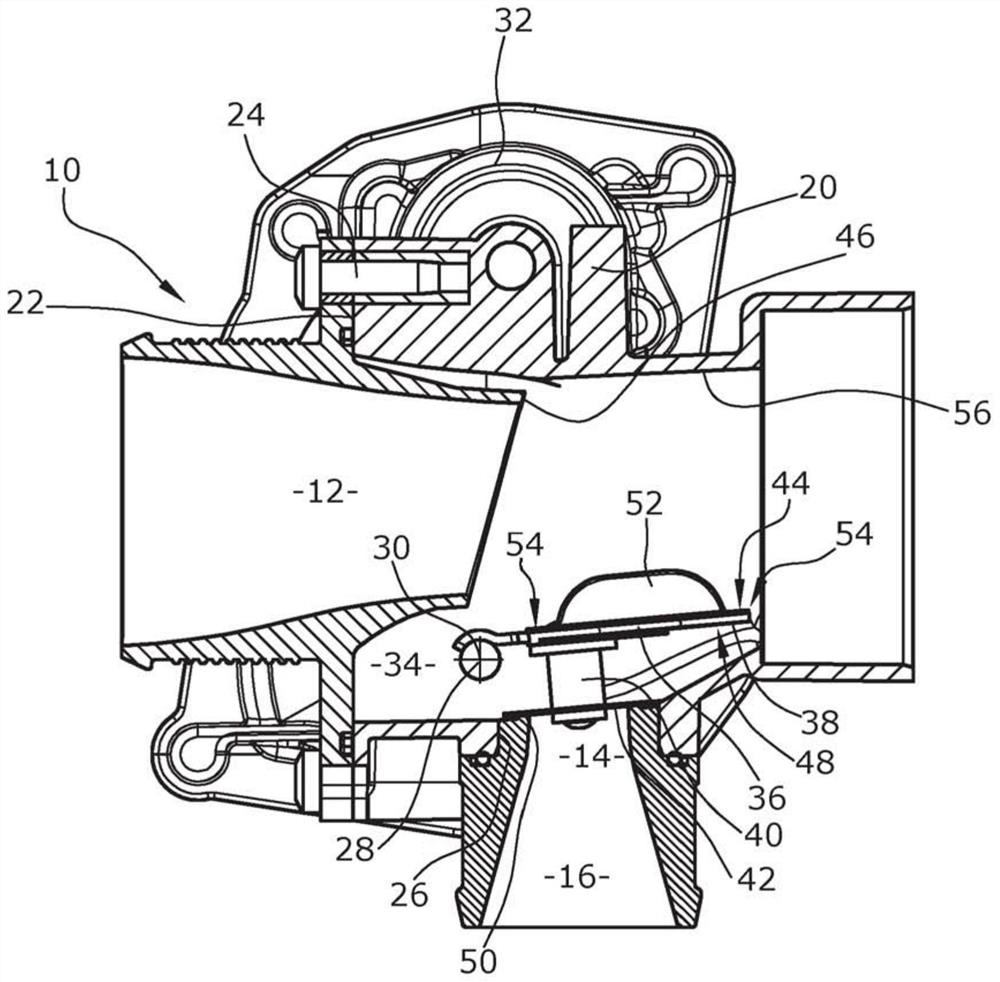
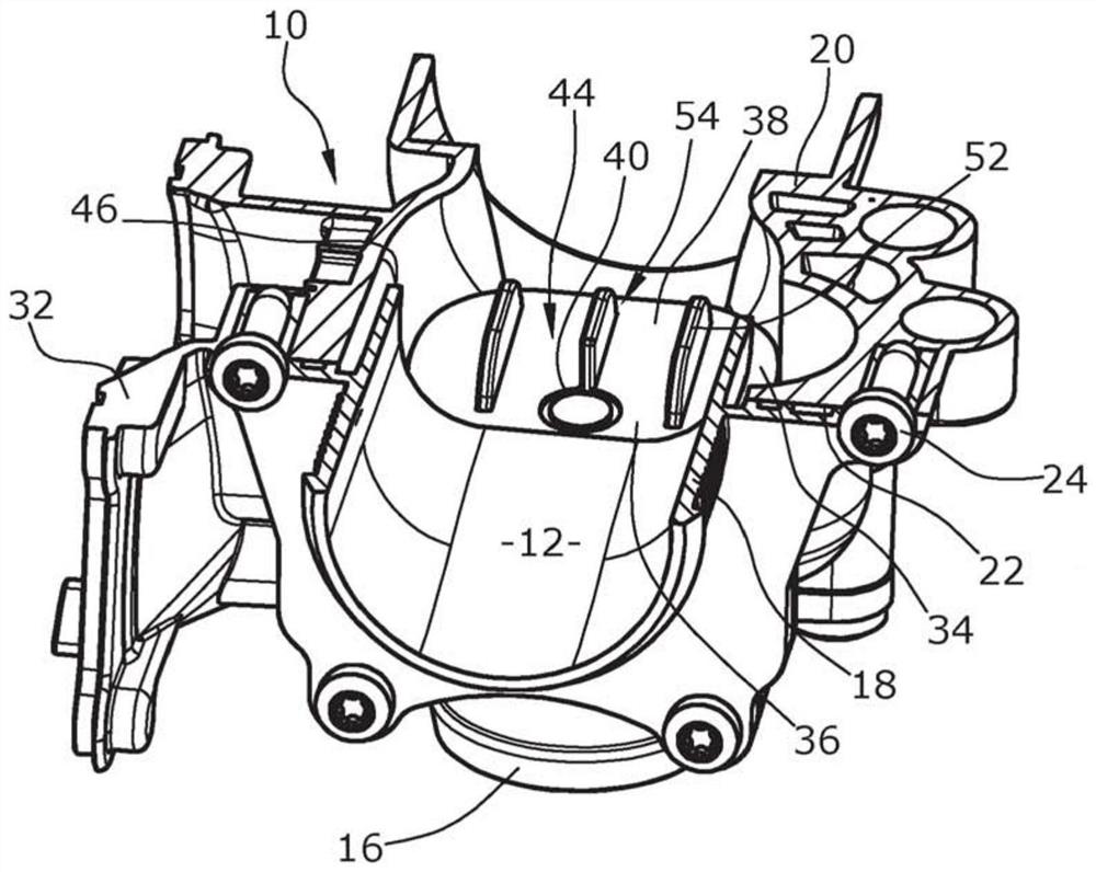
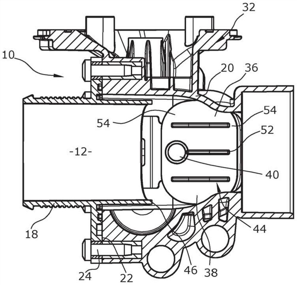
[0029] The regulating device according to the invention is formed by a housing 10 which delimits an intake line 12 and on which is formed a connection 14 for an exhaust gas recirculation line 16 . The intake line 12 extends substantially in a straight direction as far as the axial inlet of the compressor housing of the turbocharger, not shown, while the exhaust gas recirculation line 16 enters the intake line substantially perpendicular to the intake line 12 12.

[0030] The housing 10 consists of a substantially tubular first intake housing 18 , the downstream end of which is formed obliquely and at an angle α of approximately 80° relative to the central axis of the intake line 12 . . The inlet housing 18 protrudes into the mixing housing 20 with its downstream end, or is inserted into the mixing housing 20 until the flange 22 abuts, via which the inlet housing 18 is fixed on the mixing housing 20 by means of bolts 24 . housing 20.

[0031] The connection 14 of the exhaust...


PUM


Abstract

A regulating device for an internal combustion engine is known with an intake line (12), an exhaust gas recirculation line (16) opening into the intake line, a housing configured with the intake line and the exhaust gas recirculation line (10), the shaft (28) used as the axis of rotation (30), the adjustment body (36) is arranged eccentrically on the shaft, and the shaft is arranged perpendicular to the central axis of the intake pipe and the exhaust gas recirculation pipe, wherein, in In the first end position, the intake line is throttled at least upstream of the connection of the exhaust gas recirculation line, wherein the normal vector of the first surface (44) of the adjusting body (36) faces the upstream side of the intake line, and In the second end position, the exhaust gas recirculation line is closed, wherein the normal vector of the second surface ( 48 ) of the adjusting body ( 36 ) faces the exhaust gas recirculation line. However, this regulating device has the disadvantage that the increased flow resistance due to the channel throttling reduces the power of the subsequent compressor and the internal combustion engine. To solve this problem, it is provided according to the invention that guide ribs (52) are formed on the first surface (44).

Description

technical field [0001] The invention relates to a control device for an internal combustion engine, which has an intake line, an exhaust gas recirculation line leading into the intake line, and a housing in which the intake line and the exhaust gas recirculation are formed. Line, a shaft serving as the axis of rotation, on which the adjusting body is mounted eccentrically, the shaft being arranged perpendicular to the central axis of the intake line and the exhaust gas recirculation line, wherein in the first In an end position, the normal vector of the first surface of the adjusting body points to the upstream side of the intake line, in the first end position the intake line is at least throttled upstream of the connection of the exhaust gas recirculation line, and In the second end position, the normal vector of the second surface of the adjusting body points towards the exhaust gas recirculation line, in which the exhaust gas recirculation line is closed. Background tech...

Claims


Application Information

Patent Timeline
IPC IPC(8): F02M26/16F02M26/21F02M26/64F02M26/70F02M26/06F02D9/10F02D9/02
CPCF02D9/101F02D2009/0276F02M26/06F02M26/21F02M26/50F02M26/64F02M26/70F02M26/71B29L2031/7506F02D9/107
Inventor D.维尔科滕M.弗伦德C.维吉尔德A.库斯克F.A.索默霍夫H.金德尔J.克默林V.斯米尔贾诺夫斯基H.弗里德里克斯
Owner PIERBURG GMBH & CO KG NEUSS
Why Eureka
Try Eureka