Photographing control method and device thereof

A control method and position information technology, applied in the direction of non-electric variable control, control/adjustment system, three-dimensional position/channel control, etc., can solve problems such as difficult cooperation and complicated control process, and achieve smooth pictures, accurate composition, Composition-rich effects

Active Publication Date: 2018-08-31
SZ DJI TECH CO LTD
View PDF6 Cites 61 Cited by
  • Summary
  • Abstract
  • Description
  • Claims
  • Application Information

AI Technical Summary

Problems solved by technology

UAV aerial photography involves a series of operations such as camera settings, gimbal control, joystick control, and composition and viewing. , Joystick, and a series of parameters such as composition and viewfinder, the control process is more complicated
However, it is difficult for users who are not skilled in aerial photography to cooperate with the above series of parameters within a certain period of time.

Method used


Image

  • Photographing control method and device thereof
  • Photographing control method and device thereof
  • Photographing control method and device thereof

Examples


Embodiment 1

[0081] An embodiment of the present invention provides a shooting control method, which can be applied to the drone side 1 . In this embodiment, on the UAV side 1, the method can be implemented by a dedicated control device, or by a flight controller of the UAV, or by a pan / tilt controller.

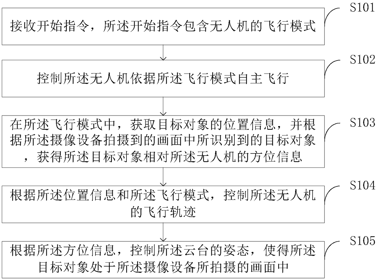
[0082] see figure 1 , the shooting control method may include the following steps:

[0083] Step S101: receiving a start instruction, the start instruction includes the flight mode of the drone;

[0084]In this embodiment, the start command can be sent from the smart terminal 2 to the drone side 1 . The smart terminal 2 may include a user interface. Optionally, the user interface is provided with an operation button for generating a start instruction, and the operation button may be a physical button or a virtual button. Specifically, when the user needs to control the autonomous flight of the drone, he can simply press the operation button to conveniently and quickly control the auton...

Embodiment 2

[0163] The embodiment of the present invention provides a shooting control method, and the method can be applied to the smart terminal 2 installed with APP. In this embodiment, the smart terminal can communicate with the drone.

[0164] see Figure 8 , the shooting method may include the following steps:

[0165] Step S801: receiving a user instruction;

[0166] Wherein, the user instruction can be directly input by the user on the smart terminal 2 . In a specific implementation manner, the smart terminal 2 includes an APP (application software) for the user to input user instructions. Optionally, the APP can be used to display the picture returned by the drone.

[0167] In some embodiments, the user instruction includes: determining the target object to be identified. In this embodiment, after the target object to be identified is determined, the method further includes: identifying feature information of the target object to be tracked in the currently displayed screen,...

Embodiment 3

[0214] Corresponding to the shooting control method in Embodiment 1, the embodiment of the present invention provides a shooting control device, which can be applied to the drone side 1 .

[0215] see Figure 11 , the shooting control device may include a first processor 11, wherein the first processor 11 is configured to execute the steps of the shooting control method described in the first embodiment above.

[0216] In this embodiment, the first processor 11 is used to communicate with the smart terminal 2, so that the first processor 11 can receive the start instruction from the smart terminal 2 and can combine the pictures taken by the drone with the unmanned Other data information etc. of the machine are sent to the intelligent terminal 2.

[0217] In this embodiment, the first processor 11 may be selected as a controller in a dedicated control device, may also be selected as a flight controller of an unmanned aerial vehicle, or may be selected as a pan-tilt controller....


PUM


Abstract

The invention provides a video picture generating method and a device thereof, wherein the method and the device are applied to an unmanned aerial vehicle. The unmanned aerial vehicle is provided witha pan / tilt which is provided with photographing equipment. The method and the device are characterized in that the method comprises the steps of receiving a starting instrument which comprises the flight mode of the unmanned aerial vehicle; making all unmanned aerial vehicle perform autonomous flight according to the flight mode; in the flight mode, acquiring position information of a target, andaccording to the target which is identified in the picture that is photographed by the photographing equipment, acquiring direction information of the target relative to the unmanned aerial vehicle;according to the position information and the flight mode, controlling the flight track of the unmanned aerial vehicle; and according to the direction information, controlling gesture of the pan / tiltso that the target is in the picture which is photographed by the photographing equipment. Without manual control of an operator, controlling to the unmanned aerial vehicle and the pan / tilt can be realized. Smoother photographed picture and more abundant and accurate picture composition are realized.

Description

technical field [0001] The invention relates to the field of image acquisition, in particular to a shooting control method and device. Background technique [0002] With the development of drone aerial photography technology, there are more and more types of drones on the market. UAV aerial photography involves a series of operations such as camera settings, gimbal control, joystick control, and composition and viewing. , Joystick, and a series of parameters such as composition and viewfinder, the control process is more complicated. However, it is difficult for users who are not skilled in aerial photography to cooperate with the above series of parameters within a period of time. Contents of the invention [0003] The invention provides a shooting control method and device. [0004] According to a first aspect of the present invention, a shooting control method is provided, which is applied to an unmanned aerial vehicle, the unmanned aerial vehicle is equipped with a ...

Claims


Application Information

Patent Timeline
IPC IPC(8): H04N5/232G05D1/10
CPCG05D1/101G06V20/176G06V20/20G06V2201/07H04N23/66B64U2101/30B64U2201/104B64U20/80B64U70/10G06V20/17B64C39/024
Inventor 钱杰苏冠华郭灼周谷越
Owner SZ DJI TECH CO LTD
Why Eureka
Try Eureka