Eureka AIR delivers breakthrough ideas for toughest innovation challenges, trusted by R&D personnel around the world.

Straw baling machine

A straw and silo technology, applied in the field of straw balers, can solve the problems of heavy equipment, material bridging, high energy consumption, and achieve the effects of simple overall structure, easy movement and reduced volume

Inactive Publication Date: 2018-09-04
李卫涛
View PDF0 Cites 5 Cited by
  • Summary
  • Abstract
  • Description
  • Claims
  • Application Information

AI Technical Summary

Problems solved by technology

The packing density of the picking and baling machine is low, the cost of material transportation is high, and it is not easy to promote
The double-cylinder hydraulic baler adopts free floor feeding, the density of the material entering the compression bin is unstable, there is serious material bridging phenomenon, and the density of grass blocks changes greatly
The three-cylinder hydraulic baler is large in size, heavy in equipment, inconvenient to move, high in energy consumption and low in efficiency

Method used


Image

  • Straw baling machine

Examples


Embodiment Construction

[0015] The present invention will be further described below in conjunction with the drawings.

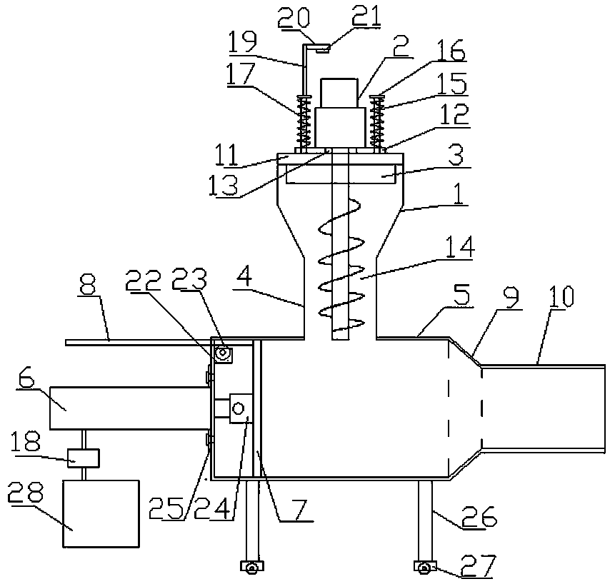
[0016] Such as figure 1 As shown, a straw baler includes a silo 1, a PLC controller, and a screw feeder 2 installed on the silo. The screw feeder 2 is composed of a screw 14 and a power mechanism that drives the screw to rotate. The mechanism can be a hydraulic motor-reducer or a motor-reducer. The screw feeder 2 can be installed vertically, obliquely or horizontally, all of which are within the protection scope of the present invention. The screw feeder 2 and PLC The controller controls the connection. The PLC controller is an existing technology. The top of the silo is provided with a feed port 3, and the bottom wall of the silo is provided with a discharge port. The discharge port is fixedly connected with a discharge pipe 4 below the silo The compression bin 5 is fixed, and the top wall of the compression bin 5 is provided with an inlet corresponding to the discharge pipe. The lo...


PUM


Abstract

The invention relates to a straw baling machine, comprising a material bin and a screw feeder. The bottom wall of the material bin is provided with a discharge pipe; a compression bin is fixed below the material bin; a hydraulic cylinder that telescopes transversely is fixed to one side of the compression bin and is in control connection with a PLC (programmable logic controller); a piston rod endof the hydraulic cylinder is extended into the compression bin and is fixedly connected with a push plate in slidable contact with the inner peripheral wall of the compression bin; the side, close tothe hydraulic cylinder, of the top end of the push plate is fixedly provided with a retaining plate horizontally arranged; the side, far away from the hydraulic cylinder, of the compression bin is connected with a squeeze bin in horn shape and having gradually decreasing diameter; the side, far away from the compression bin, of the squeeze bin is connected with a forming bin; the side, far away from the squeeze bin, of the forming bin is provided with an outlet. The screw feeder, the hydraulic cylinder and the squeeze bin are combined for use such that material compression density is higher and straw size is greatly decreased; therefore, straws are convenient to store and convey, and the whole straw baling machine is simple in structure, small in size, light in weight, low in energy consumption and convenient to move.

Description

Technical field [0001] The invention belongs to the field of agricultural equipment, and specifically relates to a straw baler. Background technique [0002] Straw is the main by-product of crops and an important biological resource for industry and agriculture. Crop stalks are rich in nutrients and can be used as fertilizers, feeds, life fuels and raw materials for industrial production, and have a wide range of uses. Due to the large area of ​​straw, the recycling rate of straw is low, and most of the straw is burned, which not only causes serious air pollution, but also wastes resources. At present, there are pick-up and strapping machines, two-cylinder hydraulic balers and three-cylinder hydraulic balers. The picking and strapping machine has low bundling density and high material transportation cost, which is not easy to promote. The double-cylinder hydraulic baler adopts free floor feeding, the material enters the compression chamber with unstable density, there is a seri...

Claims


Application Information

Patent Timeline
Patent Type & Authority Applications(China)
IPC IPC(8): A01F15/04A01F15/10A01F15/08
CPCA01F15/046A01F15/08A01F15/10
Inventor 李卫涛
Owner 李卫涛
Why Eureka
Eureka Blog
Learn More