High-shear emulsification tank

A high-shear emulsification and emulsification tank technology, which is applied in chemical instruments and methods, chemical/physical processes, mixers, etc., can solve problems such as the weight of stirring motors and shearing motors, unreasonable structural design, and large vibration of emulsification tanks , to achieve the effect of reasonable structure setting, good practicability and convenient operation

Pending Publication Date: 2018-09-04
浙江天联机械有限公司
View PDF3 Cites 1 Cited by
  • Summary
  • Abstract
  • Description
  • Claims
  • Application Information

AI Technical Summary

Problems solved by technology

[0003] The shearing emulsification tank of the prior art still has disadvantages: the structural design is unreasonable and the structure is complicated. Generally, both the stirring motor and the shearing motor are installed on the top of the emulsification tank. The stirring motor and the shearing motor are heavy, and it is inconvenient to assemble and disassemble. The maintenance operation is troublesome, and the emulsification tank vibrates greatly during operation. Due to the unreasonable structural design, the operation is inconvenient and the practicability is poor.

Method used


Image

  • High-shear emulsification tank
  • High-shear emulsification tank

Examples


Embodiment Construction

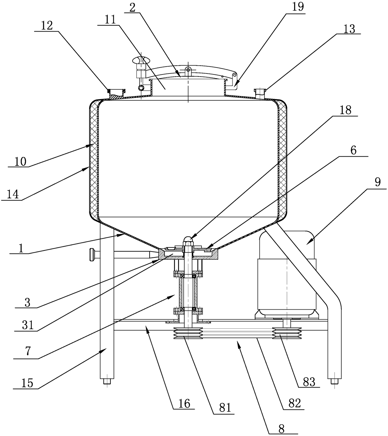
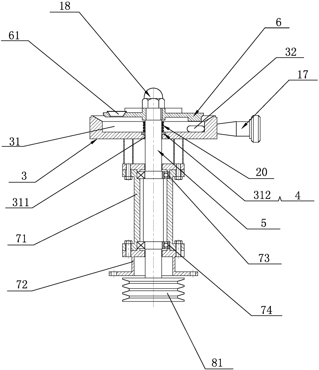
[0020] see figure 1 and figure 2 , a high-shear emulsification tank disclosed in the present invention, comprising an emulsification tank body 1, a material inlet 11 is arranged at the top middle of the emulsification tank body 1, and a flip mechanism 2 is arranged on the material inlet 11, and the emulsification tank The top left end of the main body 1 is integrally provided with a first shearing motor installation platform 12, and the top right end of the emulsification tank body 1 is integrally provided with a second shearing motor installation platform 13, and the lower end of the emulsification tank body 1 is fixedly provided with a tank body Base 3, a stirring blade installation cavity 31 is arranged in the tank body base 3, and a stirring shaft installation through hole 311 is arranged at the middle part of the bottom surface of the stirring blade installation cavity 31, and the upper port of the stirring shaft installation through hole 311 is set There is a sealing r...


PUM


Abstract

The invention discloses a high-shear emulsification tank, comprising an emulsification tank body. A material inlet is arranged at the middle of the top of the emulsification tank body and is providedwith a renovating mechanism, a first shearing motor mounting table is integrally arranged the top left end of the emulsification tank body, a second shearing motor mounting table is integrally arranged the top right end of the emulsification tank body, a tank body base is fixedly arranged at the lower end of the emulsification tank body, a stirring shaft passes through a stirring shaft mounting through hole in the tank body base, a tank bottom connecting device is arranged at the lower end of the stirring shaft, a belt transmission mechanism is arranged at the lower end of the tank bottom connecting device, a stirring motor is arranged at one end of the belt transmission mechanism, a motor shaft of the stirring motor drives the belt transmission mechanism to act so as to make the belt transmission mechanism drive the stirring shaft to rotate, and a stirring blade links to the stirring shaft. According to the technical scheme, the high-shear emulsification tank has reasonable structuraldesign, simple structure, stable work and small vibration, and is easy to maintain and convenient to operate at work.

Description

technical field [0001] The invention relates to the technical field of petrochemical equipment, in particular to a high-shear emulsification tank. Background technique [0002] At present, after the lubricating oil base oil is produced, it needs to be blended, and appropriate additives are added to blend into lubricating oil products with different performance specifications. Perform shear emulsification. [0003] The shearing emulsification tank of the prior art still has disadvantages: the structural design is unreasonable and the structure is complicated. Generally, both the stirring motor and the shearing motor are installed on the top of the emulsification tank. The stirring motor and the shearing motor are heavy, and it is inconvenient to assemble and disassemble. The maintenance operation is troublesome, and the emulsification tank vibrates greatly during operation. Due to the unreasonable structural design, the operation is inconvenient and the practicability is poo...

Claims


Application Information

Patent Timeline
Patent Type & Authority Applications(China)
IPC IPC(8): B01F7/18C10M177/00B01F15/00
CPCC10M177/00B01F27/90B01F35/00B01F2035/351B01F35/45B01F2101/39
Inventor 沈永华沈铭隆项光云季永早项鹏豪沈冠达季温特苏立任
Owner 浙江天联机械有限公司
Why Eureka
Try Eureka