Mechanical automatic loading test tube rack device

A test tube rack and mechanical technology, applied in the field of medical devices, can solve the problems of sample spillage, inability to guarantee the stability and damage of the sample test tube, and achieve the effects of avoiding spillage, reasonable structure design and good stability.

Inactive Publication Date: 2018-09-04
陈羽戈
View PDF7 Cites 2 Cited by
  • Summary
  • Abstract
  • Description
  • Claims
  • Application Information

AI Technical Summary

Problems solved by technology

[0003] Among them, loading is an important step in automatic sampling. The loading process is to push the test tube rack to the corresponding position. However, the current automatic loading test tube rack device cannot guarantee the stability of the sample test tube during transportation, which may give the sample The samples in the test tubes cause leakage or even damage, so we designed a mechanical automatic loading test tube rack device to solve the above problems

Method used


Image

  • Mechanical automatic loading test tube rack device
  • Mechanical automatic loading test tube rack device
  • Mechanical automatic loading test tube rack device

Examples


Embodiment Construction

[0022] The following will clearly and completely describe the technical solutions in the embodiments of the present invention with reference to the accompanying drawings in the embodiments of the present invention. Obviously, the described embodiments are only some, not all, embodiments of the present invention.

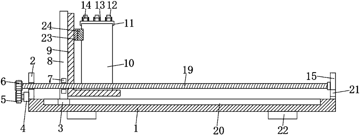
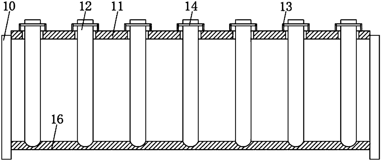
[0023] refer to Figure 1-3 , a mechanical automatic loading test tube rack device, including a base 1, the bottom of the base 1 is provided with a plurality of support blocks 22, and the bottom side walls of the plurality of support blocks 22 are provided with anti-skid lines.

[0024] The upper end of the base 1 is respectively vertically provided with a first riser 2 and a second riser 15, the side wall of the second riser 15 is rotatably connected with a threaded rod 19, and the end of the threaded rod 19 away from the second riser 15 runs through the first The side wall of the riser 2 is threadedly connected with it, the outer wall of the threaded rod 19 is fixe...


PUM


Abstract

The invention discloses a mechanical automatic loading test tube rack device which comprises a base, wherein a first vertical plate and a second vertical plate are respectively vertically arranged atthe upper end of the base, a threaded rod is rotationally connected to the side wall of the second vertical plate; one end, far away from the second vertical plate, of the threaded rod, runs through the side wall of the first vertical plate and is in threaded connection with the first vertical plate; a driven wheel is fixedly connected to the outer side wall of the threaded rod, a motor is fixedlyconnected to the side wall of the first vertical plate, a driving wheel mutually meshed with the driven wheel is fixedly connected to the tail end of the output shaft o the motor, a stripe limiting slot is formed in the upper end of the base, a limiting block is connected in the stripe limiting slot in a sliding way, a moving plate is fixedly connected to the upper end of the limiting block, andan extension plate is fixedly connected to the front side wall of the moving plate. The device is reasonable in structure design, and can ensure that test tube bodies are good in stability in delivery, thus ensuring that samples in the test tube bodies do no easily suffer from leakage and damage.

Description

technical field [0001] The invention relates to the technical field of medical instruments, in particular to a mechanical automatic loading test tube rack device. Background technique [0002] When conducting medical research, it is necessary to put some collected samples into special sample test tubes. When multiple sample test tubes are placed on the test tube rack, when the samples in the sample test tubes need to be tested and analyzed, special instruments are required. The test tube rack is loaded, pushed and unloaded to complete the automatic delivery of samples. [0003] Among them, loading is an important step in automatic sampling. The loading process is to push the test tube rack to the corresponding position. However, the current automatic loading test tube rack device cannot guarantee the stability of the sample test tube during transportation, which may give the sample The samples in the test tubes cause spillage or even damage. For this reason, we have designe...

Claims


Application Information

Patent Timeline
Patent Type & Authority Applications(China)
IPC IPC(8): B01L9/06
CPCB01L9/06
Inventor 陈羽戈
Owner 陈羽戈
Why Eureka
Try Eureka