A robot modular assembly mechanical arm

A modular, robotic arm technology, applied in the field of robotic arms, can solve the problems of narrow range of use of robotic arms, high maintenance and replacement costs, and limited use of areas, to facilitate transportation and storage, save replacement materials and costs, and versatility strong effect

Active Publication Date: 2019-04-05
浙江中驱电气有限公司
View PDF6 Cites 0 Cited by
  • Summary
  • Abstract
  • Description
  • Claims
  • Application Information

AI Technical Summary

Problems solved by technology

The existing mechanical arm is generally composed of three parts, the big arm, the small arm and the finger part. In different application fields, according to the nature of their work, these three parts of the robot mechanical arm need to be specially designed, such as large The length of the arm and the forearm, as well as the degree of bending and rotation, etc., which make the use range of a robot arm narrow, the use area is limited, the application function is single, and its maintenance and replacement costs are also high

Method used


Image

  • A robot modular assembly mechanical arm
  • A robot modular assembly mechanical arm
  • A robot modular assembly mechanical arm

Examples


Embodiment 1

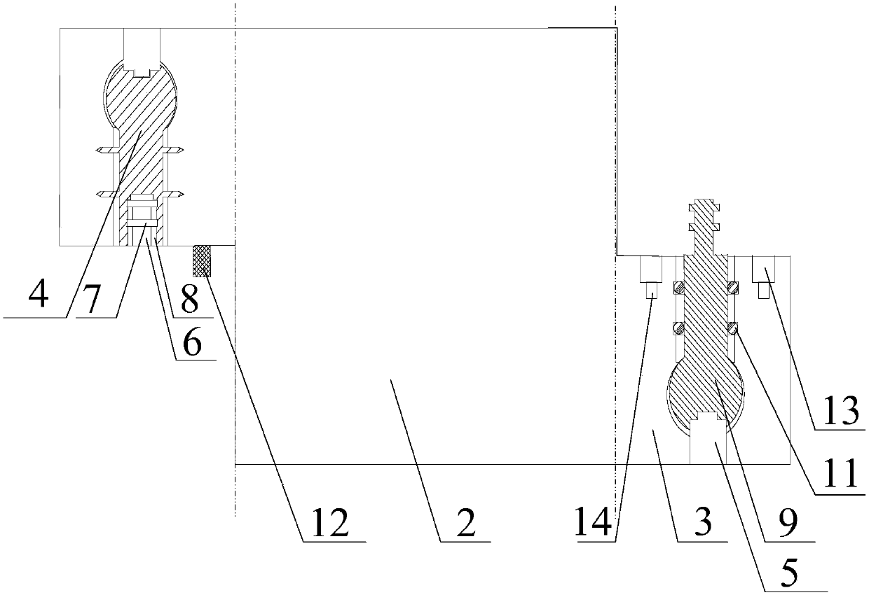
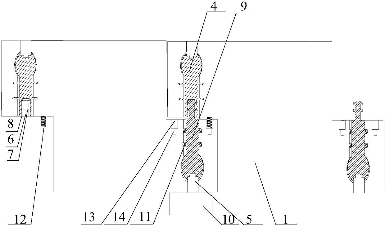
[0024] Such as Figure 1~2As shown, a robot modular assembly mechanical arm of the present invention includes an arm body, and the arm body includes a plurality of interconnected arm sections 1, and each section arm section 1 includes a rectangular block 2, on opposite sides of the rectangular block 2 One end is respectively provided with a bump 3, and one of the bumps 3 is fixed with a fixed shaft 4, and one end of the fixed shaft 4 is provided with a driving installation hole 5 communicating with the outside world, and the other end is provided with a fixing hole 6, and in the fixing hole The inner wall of 6 is provided with at least one annular groove 7 and chute 8, one end of said chute 8 communicates with the annular groove 7, the other end is flush with the mouth of the fixing hole 6, and a moving shaft is arranged in the other protruding block 3 9. One end of the moving shaft 9 protrudes from the surface of the bump 3, and the protruding end matches the fixing hole 6 an...

Embodiment 2

[0028] Such as Figure 1~2 As shown, on the basis of Embodiment 1, the end of the fixed shaft 4 or the moving shaft 9 having the drive installation hole 5 is a spherical body, and the diameter of the spherical body is 1.25 of the diameter of the wall of the fixed shaft 4 or the moving shaft 9. ~1.55 times. The above structure can effectively prevent the fixed shaft and the moving shaft from falling off from their respective protrusions; Disperse the external axial stress on the rotor, reduce the radial deformation of the connecting section of the rotor, and improve the service life of the fixed and moving shafts.

[0029] In addition, the inventor tested the relationship between the diameter of the spherical end of the rotor and the radial deformation of the rotor, and applied an axial stress test of 170MP to the rotor. Some test results are as follows:

[0030]

[0031] From the table above, it can be seen that if the diameter of the spherical body is designed to be 1.25...

Embodiment 3

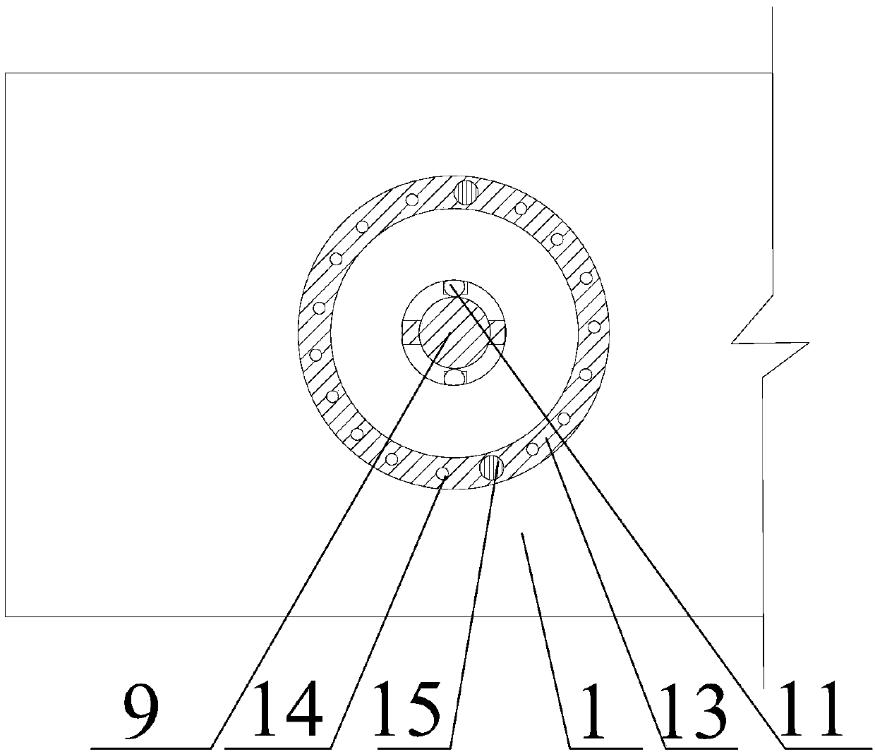
[0033] Such as Figure 1~3 As shown, on the basis of Embodiment 1, a positioning rod 12 is also provided on the bump 3 where the fixed rotating shaft 4 is located, and an annular positioning groove 13 is also opened on the convex block 3 where the moving rotating shaft 9 is located. The centerline coincides with the central axis of the moving shaft 9, and the annular positioning groove 13 is filled with lubricating oil. There are several threaded holes 14 on the bottom surface of the annular positioning groove 13, and the threaded holes 14 are equidistantly arranged around the centerline of the annular positioning groove 13, and also include two stop screws 15, the diameter of the stop screw 15 is the same as that of the ring. The inner diameters of the positioning grooves 13 are equally large. The above structure helps the fixed shaft 4 and the moving shaft 6 to be aligned and connected, and the position after the connection of the fixed shaft 4 and the moving shaft 6 is lim...


PUM


Abstract

The invention discloses a modular assembly mechanical arm of a robot, which comprises an arm body, the arm body includes a plurality of interconnected arm sections, each arm section includes a rectangular block, and a rectangular block is respectively arranged at two opposite ends One of the bumps is fixed with a fixed shaft, one end of the fixed shaft is provided with a driving installation hole communicating with the outside world, and the other end is provided with a fixing hole, and at least one annular groove and sliding hole are opened on the inner wall of the fixing hole. One end of the chute communicates with the annular groove, the other end is flush with the fixed orifice, and a moving shaft is arranged in the other bump, and one end of the moving shaft protrudes from the surface of the bump, and the protruding end It is matched with the fixed hole and can enter the annular groove along the chute and be restricted in the annular groove; the present invention is assembled with a detachable module structure, which can be freely assembled and extended according to the working environment, with higher flexibility and versatility Stronger, can adapt to a variety of operations.

Description

technical field [0001] The invention relates to the field of robot arms, in particular to a robot modular assembly robot arm. Background technique [0002] Robotic manipulator is a mechanical device that can automatically complete the transmission or operation of objects (such as materials, workpieces, parts or tools, etc.) according to established procedures or requirements. It can partially replace human manual labor and complete more complex tasks. Operation. Robotic manipulators are widely used in semiconductor manufacturing, industry, medical, military, and space exploration and other fields. The existing mechanical arm is generally composed of three parts, the big arm, the small arm and the finger part. In different application fields, according to the nature of their work, these three parts of the robot mechanical arm need to be specially designed, such as large The length of the arm and forearm, as well as the degree of bending and rotation, etc., make a robot arm ...

Claims


Application Information

Patent Timeline
Patent Type & Authority Patents(China)
IPC IPC(8): B25J9/08B25J17/00B25J18/00
CPCB25J9/08B25J17/00B25J18/00
Inventor 周小燕
Owner 浙江中驱电气有限公司
Why Eureka
Try Eureka