Plastic foam cutting device
A cutting device and plastic foam technology, applied in the fields of plastic foam cutting and plastic foam manufacturing, can solve problems such as poisoning reactions and endangering workers' health, and achieve the effects of reducing the production of aromatic hydrocarbons, protecting health, and increasing production speed
Active Publication Date: 2018-09-04
遵义锦鸿富科技发展有限公司
View PDF12 Cites 3 Cited by
- Summary
- Abstract
- Description
- Claims
- Application Information
AI Technical Summary
Problems solved by technology
The raw material of plastic foam is generally polystyrene, and the cutting of plastic foam boards is generally to heat the cutter first. When cutting, the heat will melt the plastic foam boards in contact with the cutter, but due to the high temperature, the heat will still Melt the plastic foam around the cutting site to produce a variety of aromatic hydrocarbons, which will cause poisoning reactions when people inhale these aromatic hydrocarbons, which will greatly endanger the health of workers
Method used
View moreImage
Smart ImageViewing Examples

Examples
Embodiment Construction
[0023] Below in conjunction with accompanying drawing and specific embodiment the present invention will be described in further detail:
Login to View More PUM
 Abstract
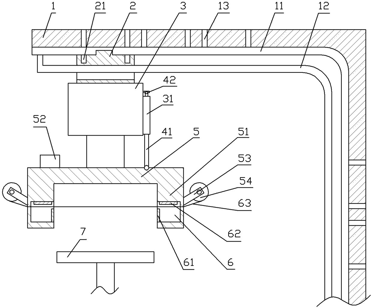
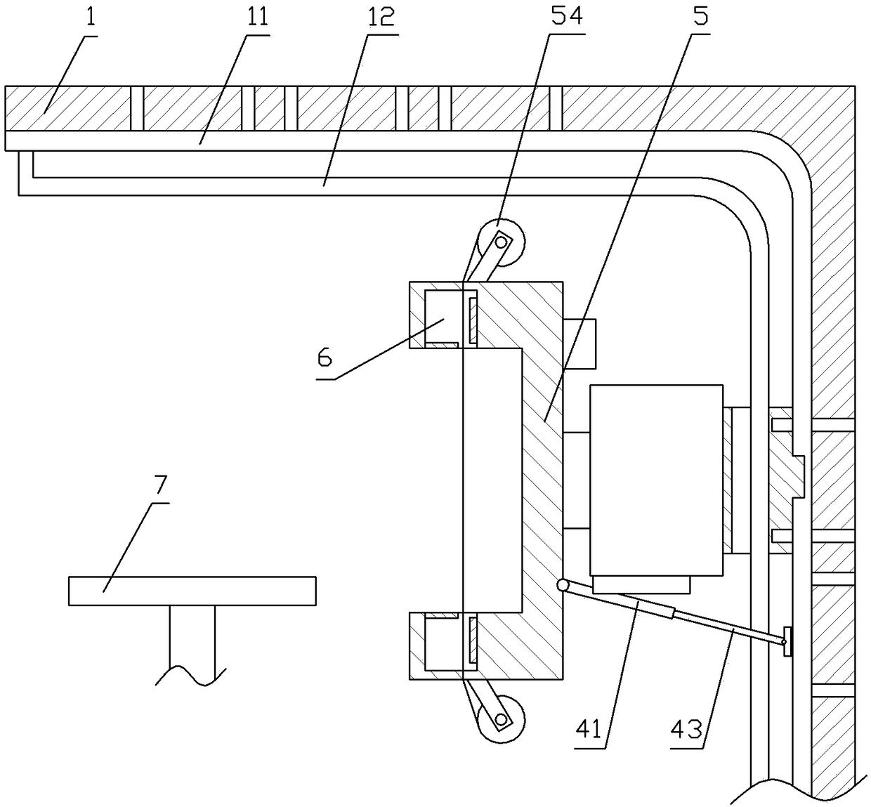
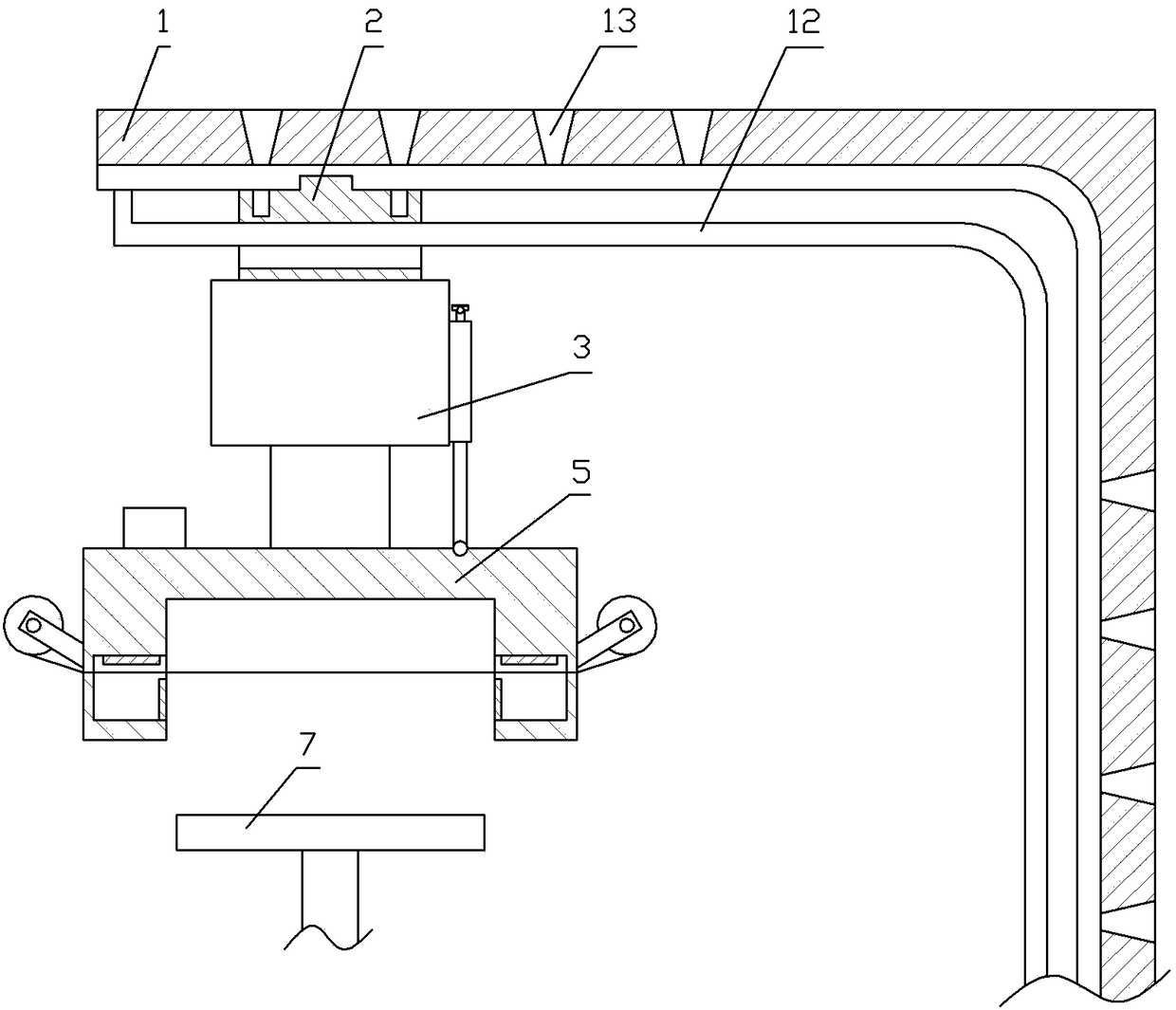
The invention relates to the field of manufacturing of plastic foams, and particularly discloses a plastic foam cutting device. The plastic foam cutting device comprises a rack, a moving mechanism andcutting mechanisms, wherein the rack is provided with a track; the moving mechanism comprises a sliding block, a hydraulic jack and a mounting seat; fixing holes are formed in the rack; positioning holes are formed in the sliding block; the mounting seat comprises a base and supports; the two cutting mechanisms are oppositely arranged along the base; each cutting mechanism comprises a heating piece, a stepping motor and winding rolls; a groove is formed in each support; a heating piece is fixed in each groove; a cutting rope is arranged on the mounting seat; the cutting rope penetrates through the side wall, which is opposite to an opening, of each groove; and two ends of the cutting rope are separately fixed on the two winding rolls; a fan is fixed on the mounting seat; and a worktable is arranged on the rack. According to the scheme, plastic foam melting is relieved in a cutting process by the cutting device.
Description
technical field [0001] The invention relates to the field of plastic foam manufacturing, in particular to the field of plastic foam cutting. Background technique [0002] Plastic foam is a kind of polymer material formed by a large number of gas micropores dispersed in solid plastic. It has the characteristics of light weight, heat insulation, sound absorption, shock absorption, corrosion resistance, etc., and is easy to form and has good water resistance. Price It is also very cheap, so it is widely used in packaging, heat preservation, waterproof, heat insulation, shock absorption and other fields. It is one of the most widely used plastics in the world today. [0003] The preparation of plastic foam generally first introduces gas into liquid or molten plastic to generate micropores; then the micropores grow to a certain volume; then the microporous structure is fixed by physical or chemical methods to obtain plastic foam. However, companies that need to use plastic foam ...
Claims
Login to View More Application Information
Patent Timeline
 IPC IPC(8): B26F3/12B26D5/04B26D7/08B26D7/18B26D7/26
CPCB26D5/04B26D7/08B26D7/088B26D7/1854B26D7/2614B26F3/12
Inventor 申天玖
Owner 遵义锦鸿富科技发展有限公司
Features
- R&D
- Intellectual Property
- Life Sciences
- Materials
- Tech Scout
- Unparalleled Data Quality
- Higher Quality Content
- 60% Fewer Hallucinations
Learn More Browse by: Latest US Patents, China's latest patents, Technical Efficacy Thesaurus, Application Domain, Technology Topic, Popular Technical Reports.
© 2025 PatSnap. All rights reserved.Legal|Privacy policy|Modern Slavery Act Transparency Statement|Sitemap|About US| Contact US: help@patsnap.com