LED projector

A technology of LED flood light and light-emitting plate, which is applied in the direction of light source, electric light source, point light source, etc., can solve the problems of poor heat dissipation effect, decrease in luminous efficiency and luminous quality, affecting the normal operation of LED, etc., and achieve good heat dissipation effect. Effect

Inactive Publication Date: 2008-06-25
上海坤硕光电科技有限公司
View PDF0 Cites 12 Cited by
  • Summary
  • Abstract
  • Description
  • Claims
  • Application Information

AI Technical Summary

Problems solved by technology

[0002] Due to the advantages of energy saving and environmental protection, LEDs have been widely used in various lamps, but because the luminous efficiency and luminous quality of LEDs will decrease with the increase of temperature, especially when the number of LEDs is large, it will generate a lot of light. If the heat is not dissipated in time, it will seriously affect the normal operation of the LED. Therefore, most of the floodlights that use LEDs as light sources are specially designed with a heat dissipation st

Method used


Image

  • LED projector
  • LED projector
  • LED projector

Examples


no. 1 example

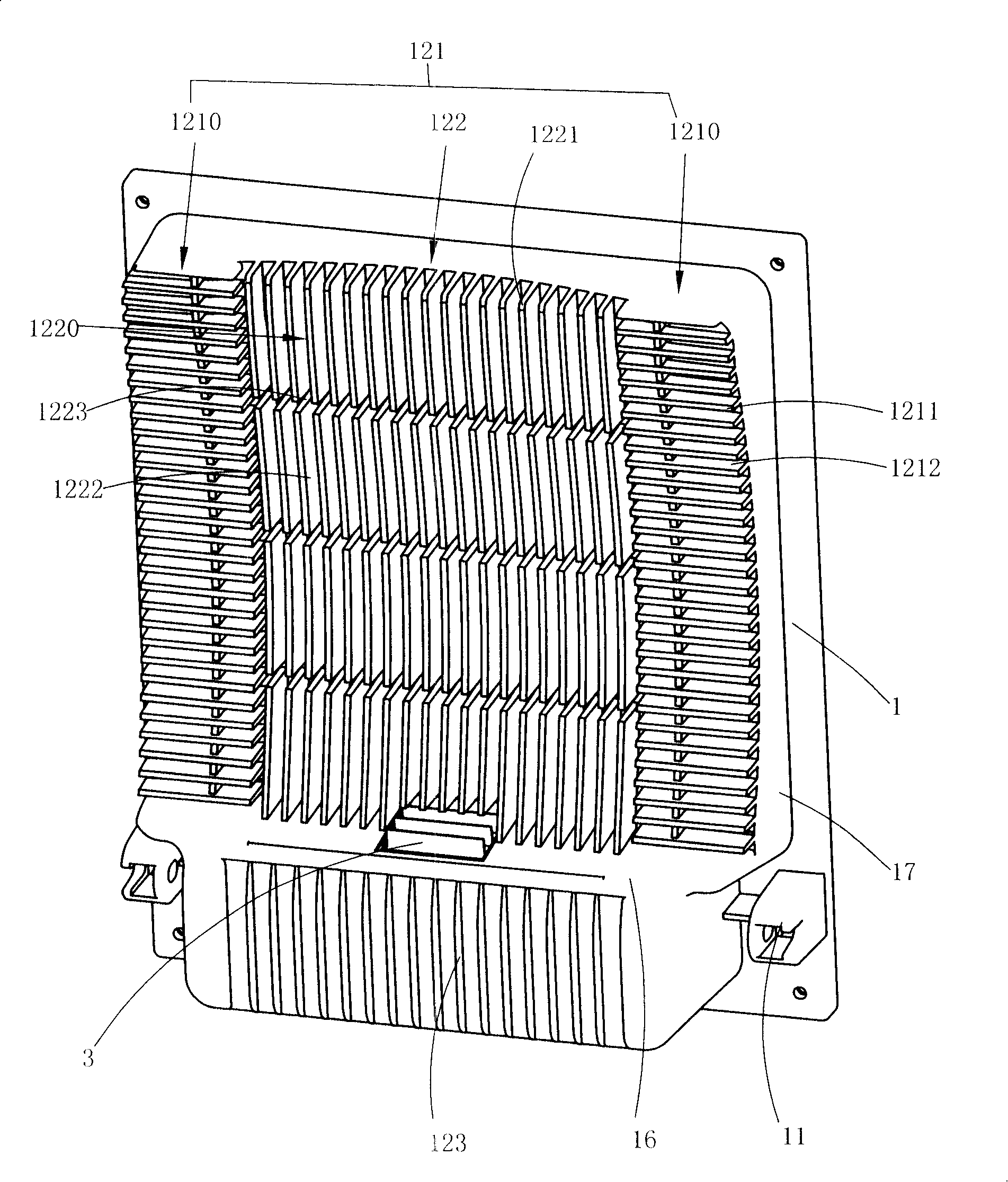
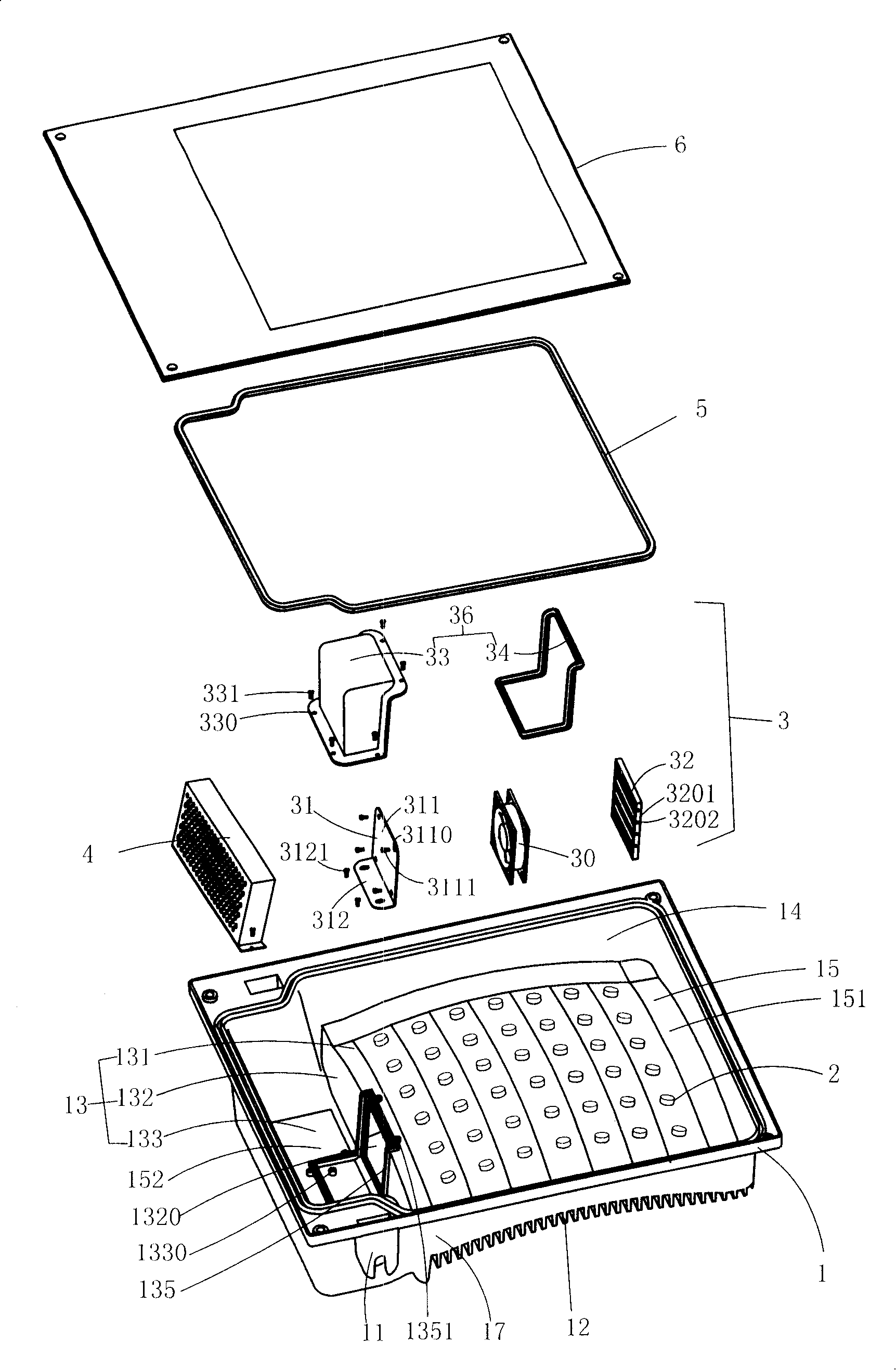
[0025] see figure 1 to Figure 7. The LED floodlight of the present invention mainly includes a housing 1 , an LED 2 , a cooling device 3 , a power supply device 4 , a sealing ring 5 of a light-emitting plate and a light-emitting plate 6 . Wherein, the LED2 is housed in the casing 1 and is electrically connected to the power supply device 4; the cooling device 3 is installed on the casing 1 and is electrically connected to the power supply device 4, and is mainly used for forced cooling of the casing 1; the power supply device 4. Provide the LED2 and the cooling device 3 with the required operating voltage; the light-emitting board 6 is installed on the housing 1 and the LED2 is sealed in the housing 1 by means of the sealing ring 5 of the light-emitting board.

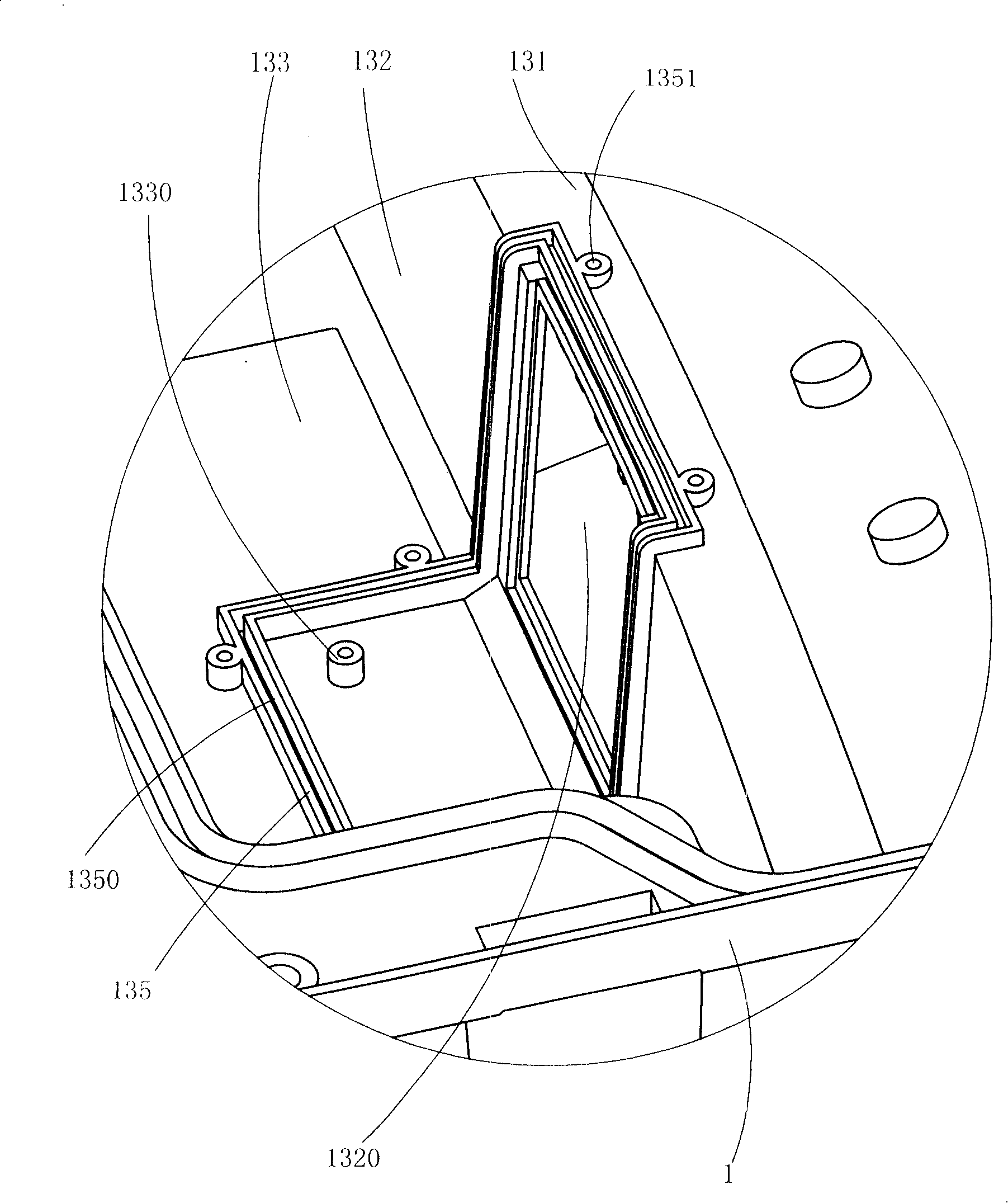
[0026] The housing 1 is made of a material with good thermal conductivity (for example, aluminum), and the housing 1 includes a fixed portion 11, a heat sink 12, a bottom wall 13, four side walls 14, and a wall enclos...

no. 2 example

[0038] see Figure 8 . This embodiment differs from the first embodiment only in the specific structure of the protective device. In this embodiment, the protection device 32' does not have the function of preventing rainwater from entering, but plays a role of safety protection (such as preventing the cooling fan from causing damage to the opponent when the hand is stretched in), and it is mainly composed of the main body frame 320' and the main body frame. A protective net 322' of several mesh holes 3220'. When the cooling fan 30' works, the wind enters the gap of the heat sink through the mesh 3220', and the heat on the surface of the heat sink is quickly dissipated to achieve the effect of rapid forced cooling. The four side walls 3201' of the main body frame 320' and the protective net 322' form a filter housing space 323', which can contain a filter sheet or a drying sheet with good air permeability, which is mainly used for filtering flying dust or absorbing moisture....


PUM


Abstract

The invention discloses an LED spot light which comprises a shell, a plurality of LEDs, a power source device and a light emitting plate. The shell is provided with a plurality of cooling fins; the LEDs are received in the shell and electrically connected with the power source device; the light emitting plate is fixed on the shell and seals the LEDs between the shell and the light emitting plate; a gap is formed between two adjacent cooling fins. Moreover, the LED spot light is also provided with a cooling fan arranged on the position where the cooling fan can make the air flow easily in at least part of gaps.

Description

【Technical field】 [0001] The invention relates to an LED floodlight, more precisely, to an LED floodlight with good heat dissipation effect. 【Background technique】 [0002] Due to the advantages of energy saving and environmental protection, LEDs have been widely used in various lamps, but because the luminous efficiency and luminous quality of LEDs will decrease with the increase of temperature, especially when the number of LEDs is large, it will generate a lot of light. If the heat is not dissipated in time, it will seriously affect the normal operation of the LED. Therefore, most of the floodlights that use LEDs as light sources are specially designed with a heat dissipation structure to dissipate the heat generated by the LED as quickly as possible to keep the LED luminous. efficiency and luminous quality. An existing heat dissipation structure with a better heat dissipation effect is to arrange heat sinks outside the floodlight to dissipate the heat generated by the L...

Claims


Application Information

Patent Timeline
IPC IPC(8): F21S2/00F21V29/02F21Y101/02F21K9/20F21V29/67F21V29/76F21Y115/10
Inventor 楼红献
Owner 上海坤硕光电科技有限公司
Why Eureka
Try Eureka