Eureka AIR delivers breakthrough ideas for toughest innovation challenges, trusted by R&D personnel around the world.

A method for installing catenary column foundations on railway steel-concrete composite beams

A technology of steel-concrete combined beam and installation method, which is applied in basic structure engineering, construction, etc., can solve the problems of low construction efficiency, many restrictive conditions, and difficult construction, so as to improve the quality of pouring molding, facilitate hoisting and installation, and save energy. material effect

Active Publication Date: 2020-07-28
CHINA RAILWAY ERYUAN ENG GRP CO LTD
View PDF3 Cites 0 Cited by
  • Summary
  • Abstract
  • Description
  • Claims
  • Application Information

AI Technical Summary

Problems solved by technology

[0004] The purpose of the present invention is to overcome the above-mentioned deficiencies such as many restrictive conditions, high construction difficulty, high cost, low construction efficiency and poor quality when installing catenary foundations on steel-concrete bridges in the prior art, and to provide a railway steel Installation Method of Catenary Column Foundation on Concrete Combined Beam

Method used


Image

  • A method for installing catenary column foundations on railway steel-concrete composite beams
  • A method for installing catenary column foundations on railway steel-concrete composite beams
  • A method for installing catenary column foundations on railway steel-concrete composite beams

Examples


Embodiment 1

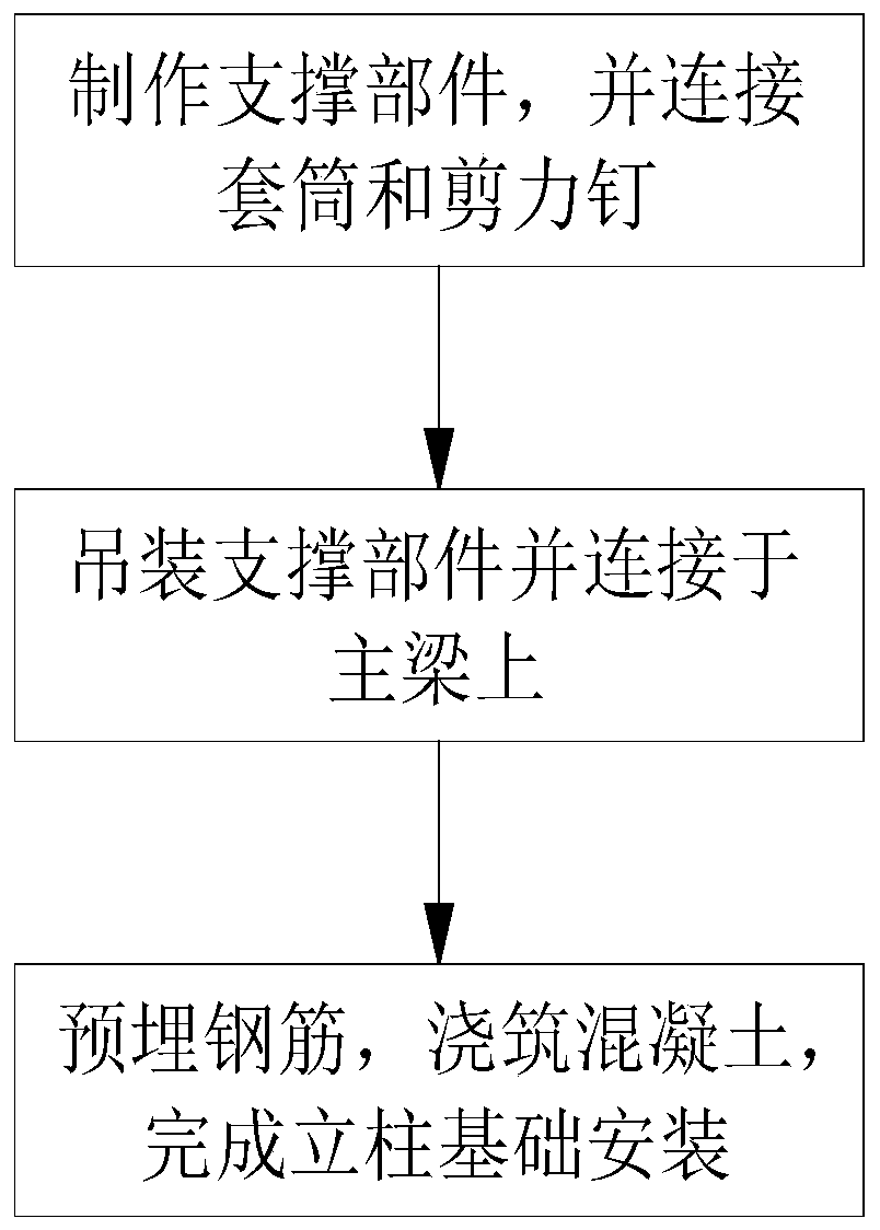
[0037] Such as figure 1 As shown, the installation method of catenary column foundation on a kind of railway steel-concrete combined beam of the present invention comprises the following steps:

[0038] Step 1, making a supporting part, connecting several sleeves and several shear nails 5 to the top of the supporting part, and all the sleeves are arranged around the installation place of the column 1;

[0039] Step 2, hoisting and connecting all the supporting components to the main beam 2;

[0040] Step 3: Set up pre-embedded steel bars on the tops of all the supporting components and the top of the main beam 2, and pour concrete on the tops of the supporting components and the top of the main beam 2 to form a reinforced concrete layer 3, and complete the installation of the column foundation.

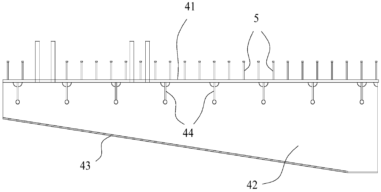
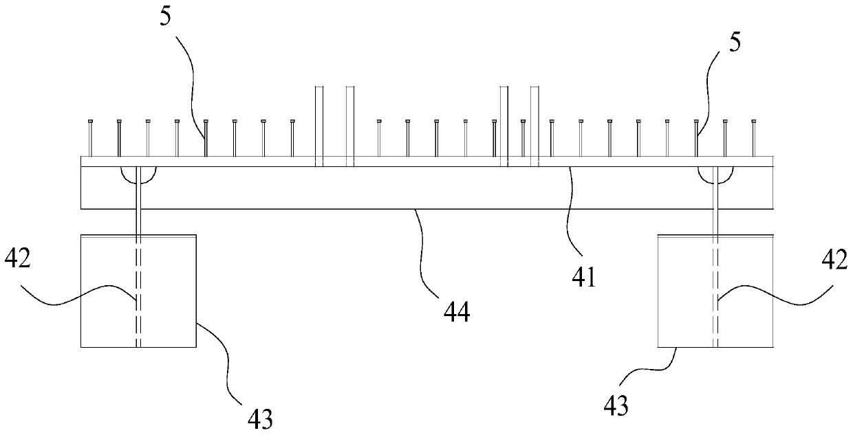
[0041] First assemble the supporting parts, the supporting parts include a top plate 41, a web 42 and a bottom plate 43 of steel structure, two of the webs 42 are arranged below the ...


PUM


Abstract

The invention discloses an installation method of a column foundation of an overhead contact system on a railway steel-concrete composite girder. The installation method of the column foundation of the overhead contact system on the railway steel-concrete composite girder comprises the steps of assembling, lifting and installing supporting parts, then embedding reinforcing steel bars on the top parts of the all supporting parts and the top part of a main girder, pouring, and accomplishing the installation of the column foundation. By adopting the method, the column foundation of the overhead contact system can be conveniently constructed, the pouring forming quality of a concrete layer is effectively improved, temporary construction measures such as independently arranging a template are reduced, the installation efficiency and the quality of the column foundation are effectively improved, the construction period is shortened, the lifting and the installing of follow-up stand columns can be carried out conveniently, the perpendicularity and the stability of the stand columns are favorably ensured, the occurrence of the phenomena of rod collapse and sedimentation is avoided, reinforcing steel bars on flanges of a bridge floor have no need to be densified, the design strength and the construction difficulty are effectively reduced, materials are favorably saved, the increase of the construction cost of bridge engineering is avoided, installation positions of the stand columns can be planned conveniently, the operating quality of the contact system is improved, the economicalefficiency is improved, and the safety of a railway power transmission line is improved.

Description

technical field [0001] The invention relates to the technical field of railway steel-concrete combined beams, in particular to a method for installing catenary column foundations on railway steel-concrete combined beams. Background technique [0002] The steel-concrete composite beam is a new type of structure formed by combining two materials with different properties, steel and concrete. It is a reasonable combination of steel and concrete, which gives full play to the advantages of high tensile strength of steel, good plasticity and good compressive performance of concrete, and can make up for each other's shortcomings. Therefore, in modern bridge structures, steel-concrete combined beams are more It has become one of the main directions of bridge development. In recent years, electrified railways have become the mainstream type of modern railways, and are widely used in the construction of high-speed railways and urban rail transit. Many non-electrified railways have al...

Claims


Application Information

Patent Timeline
Patent Type & Authority Patents(China)
IPC IPC(8): E02D27/42
CPCE02D27/42
Inventor 游励晖易大伟余浪黄毅许志艳廖文键许敏陈克坚何庭国田壮
Owner CHINA RAILWAY ERYUAN ENG GRP CO LTD
Why Eureka
Eureka Blog
Learn More