Coupled interlocking ball valve structure

A technology of locking the ball and the valve body, which is applied in the field of double interlocking ball valve structure, can solve the problems of reducing the service life of the ball valve, leakage at the pipeline connection, and easy damage of the opening and closing mechanism, so as to increase air tightness, reduce leakage rate, The effect of reducing the force

Inactive Publication Date: 2018-09-04
湖州锁控阀门有限公司
View PDF1 Cites 5 Cited by
  • Summary
  • Abstract
  • Description
  • Claims
  • Application Information

AI Technical Summary

Problems solved by technology

[0004] The purpose of the present invention is to provide a double interlocking ball valve structure to solve the problem that the opening and closing mechanism of the ball valve proposed in the above background technology is easily damaged, reducing the service life of the ball valve and prone to leakage at the joint of the pipeline, resulting in waste of resources and increased use. cost problem

Method used


Image

  • Coupled interlocking ball valve structure
  • Coupled interlocking ball valve structure
  • Coupled interlocking ball valve structure

Examples


Embodiment Construction

[0018] The following will clearly and completely describe the technical solutions in the embodiments of the present invention with reference to the accompanying drawings in the embodiments of the present invention. Obviously, the described embodiments are only some, not all, embodiments of the present invention. Based on the embodiments of the present invention, all other embodiments obtained by persons of ordinary skill in the art without making creative efforts belong to the protection scope of the present invention.

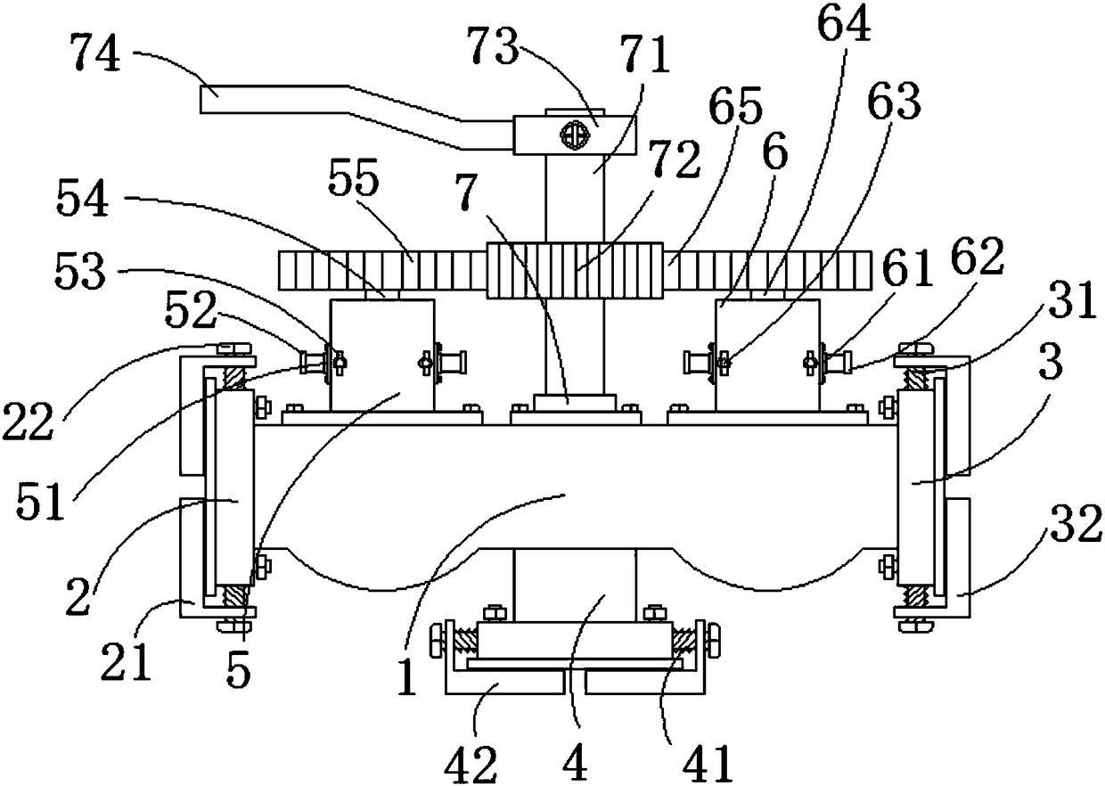
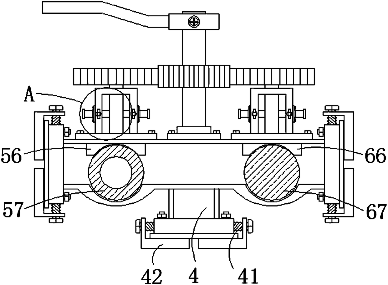
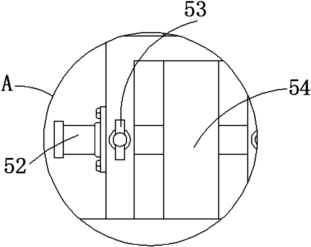
[0019] see Figure 1-Figure 3 As shown, the present invention provides the following technical solutions: a double interlock ball valve structure, including a valve body 1, a first connecting pipe 2 is installed at one end of the valve body 1, which plays the role of connecting pipelines, and a second connecting pipe 2 is installed at the other end. The connecting pipe 3 plays the role of connecting the pipes. The first adjusting bolt 22 is installed on both s...


PUM


Abstract

The invention discloses a coupled interlocking ball valve structure. The coupled interlocking ball valve structure comprises a valve body, a first connecting pipe is mounted at one end of the valve body, and a second connecting pipe is mounted at the other end of the valve body; first adjusting bolts are mounted on the two sides of the first connecting pipe and sleeved with first sealing cushions,and second adjusting bolts are mounted on the two sides of the second connecting pipe and sleeved with second sealing cushions; and a bottom connecting pipe is mounted at the bottom of the valve body, and bottom adjusting bolts are mounted on the two sides of the bottom of the bottom connecting pipe and sleeved with bottom sealing cushions. The coupled interlocking ball valve structure is provided with a first clamping rod, a first fixing rod, a second clamping rod and a second fixing rod, after a user uses a ball valve, the first fixing rod and the second fixing rod are pulled out correspondingly, the first clamping rod is inserted into a first valve pipe, the first fixing rod is inserted into the first clamping rod, and the service life of the ball valve is prolonged.

Description

technical field [0001] The invention belongs to the technical field of ball valve structure, and in particular relates to a double interlocking ball valve structure. Background technique [0002] Ball valve, the opening and closing part (ball) is driven by the valve stem and rotates around the ball valve axis. It can also be used for fluid adjustment and control. The ball valve (ball valve) came out in the 1950s. With the rapid development of science and technology, the continuous improvement of production technology and product structure, in just 40 years, it has rapidly developed into a major valve category. In western industrially developed countries, the use of ball valves is increasing year by year. . [0003] In the Chinese patent No. 201711013404.4, a split-type interconnected interlocking ball valve is disclosed. This patent achieves the purpose of easy disassembly by splitting the valve body into a left valve body and a right valve body. However, the ball valve in ...

Claims


Application Information

Patent Timeline
Patent Type & Authority Applications(China)
IPC IPC(8): F16K5/06F16K27/06F16K31/53F16K35/10
CPCF16K5/0647F16K5/0663F16K27/067F16K31/535F16K35/10
Inventor 梁世添
Owner 湖州锁控阀门有限公司
Why Eureka
Try Eureka