Valve protection device

A protection device, valve technology, applied in the direction of valve device, valve details, valve shell structure, etc., can solve the problem of increasing the lock structure and unable to protect the valve, etc.

Inactive Publication Date: 2018-09-04
南京盈博医药生物技术创新研究院有限公司 +1
View PDF5 Cites 3 Cited by
  • Summary
  • Abstract
  • Description
  • Claims
  • Application Information

AI Technical Summary

Problems solved by technology

[0002] For example, Patent No. CN201720701285.0 is a valve protection device, which relates to the field of mechanical safety and includes a housing and a protective cover. The housing is cylindrical, and a round hole is opened at the bottom of the housing. The outer extension forms an annular flange; the protective cover is cylindrical, and the inner edge of th

Method used


Image

  • Valve protection device
  • Valve protection device
  • Valve protection device

Examples


specific Embodiment approach 1

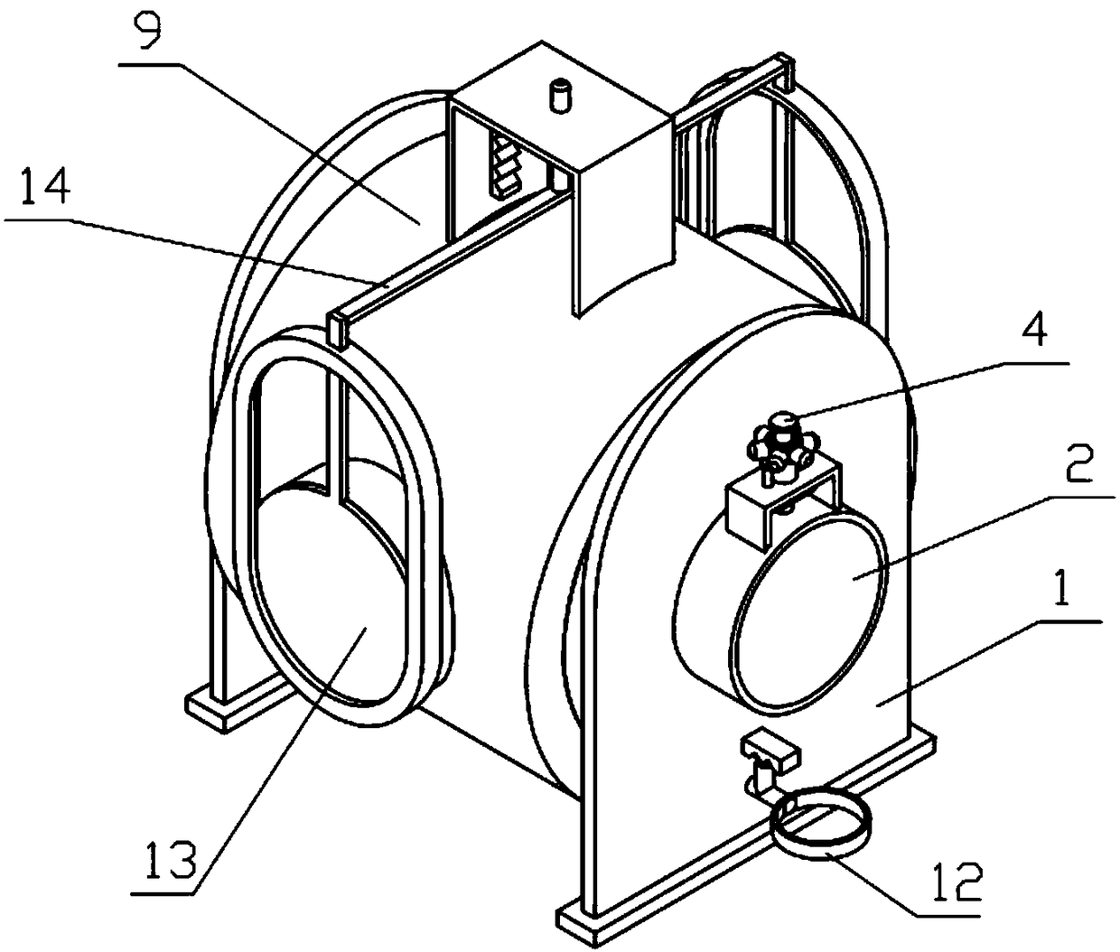
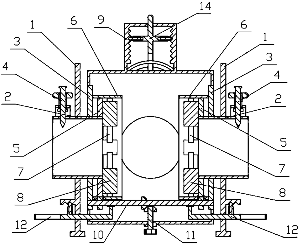
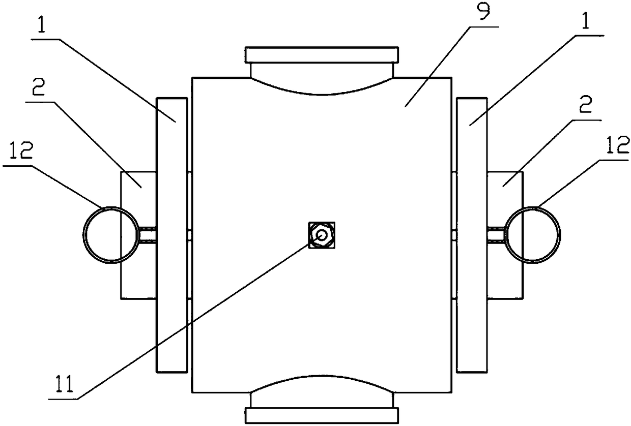
[0039] Combine below Figure 1-20 Describe this embodiment, a valve protection device, including a side plate 1, a support cylinder 2, a support plate 3, a mounting nail 4, a spiral threaded plate 5, a mounting cylinder 6, an arc plate 7, a clamping slider 8, an overall Connecting cylinder 9, transmission mechanism 10, installation mechanism 11, control mechanism 12, baffle plate 13 and buckle mechanism 14, described side plate 1, support cylinder 2, support plate 3, installation nail 4, spiral threaded plate 5, installation Both the cylinder 6 and the control mechanism 12 are provided with two symmetrically left and right, the two support cylinders 2 are fixedly connected to the two side plates 1 respectively, the two support plates 3 are fixedly connected to the two side plates 1 respectively, and the two mounting nails 4 are connected to the outer sides of the two support cylinders 2 through threads respectively, and the two scroll-shaped threaded plates 5 are respectively ...

specific Embodiment approach 2

[0040] Combine below Figure 1-20 Describe this embodiment, this embodiment will further explain Embodiment 1, the side plate 1 includes a side plate body 1-1, a W-shaped block 1-2 and a circular through hole 1-3, and the W-shaped block 1- 2. Fixedly connected to the side plate body 1-1, the circular through hole 1-3 is arranged on the side plate body 1-1, and the circular through hole 1-3 is located at the lower end of the W-shaped block 1-2; the W-shaped card Two clamping positions are provided on the block 1-2.

specific Embodiment approach 3

[0041] Combine below Figure 1-20 Describe this embodiment, this embodiment will further explain the second embodiment, the support cylinder 2 includes a support cylinder 2-1, a door-shaped bracket 2-2, a rotating cylinder 2-3 and a hexagonal handle 2-4, the door-shaped The bracket 2-2 is fixedly connected to the supporting cylinder 2-1, the lower end of the rotating cylinder 2-3 is rotatably connected to the upper end of the door-shaped bracket 2-2, and the hexagonal handle 2-4 is fixedly connected to the upper end of the rotating cylinder 2-3. The two support cylinders 2-1 are respectively fixedly connected to the two side plates 1-1, and the two support plates 3 are respectively fixedly connected to the two support cylinders 2-1; Pipelines are installed together to ensure that the device can be installed on the pipeline of the valve. When the device is placed on the pipelines on both sides, the pipeline valve is located at the middle end of the integral connection cylinder ...


PUM


Abstract

The invention relates to a protection device, in particular to a valve protection device. The valve protection device comprises side plates, supporting barrels, supporting plates, installation nails,spiral thread plates, installation barrels, arc-shaped barrels, clamping sliding blocks, an overall connection barrel, a transmission mechanism, an installation mechanism, control mechanisms, bafflesand a buckle mechanism. The device can be installed along with a pipe valve when the pipe valve is installed to protect the pipe valve, and accidents caused by accident push of the valve are prevented; the eight clamping sliding blocks are made to slide in eight clamping sliding rails formed by the eight arc-shaped plates through rotation of the installation mechanism, the eight clamping sliding blocks clamp pipes on the two sides of the valve, it is guaranteed that relative displacement cannot occur, the eight clamping sliding blocks can clamp the pipes different in size, when the diameters of the pipes on the two sides of the pipe valve are different, the transmission manner in the transmission mechanism is changed by manually adjusting the control mechanisms, and rotation of the spiralthread plates on the two sides is controlled.

Description

technical field [0001] The invention relates to a protection device, more specifically a valve protection device. Background technique [0002] For example, the patent number CN201720701285.0 is a valve protection device, which relates to the field of mechanical safety, and includes a housing and a protective cover. The outer extension forms an annular flange; the protective cover is cylindrical, and the inner edge of the bottom cooperates with the outer side of the annular flange to form a storage space; this solution has a simple structure and low processing cost, and can be applied to most common The valve structure and the lock structure are added to better guarantee the safety; the disadvantage of this utility model is that it cannot protect the valve installed on the pipeline. Contents of the invention [0003] The purpose of the present invention is to provide a valve protection device, which can protect the valves installed on the pipeline from accidents, can prot...

Claims


Application Information

Patent Timeline
IPC IPC(8): F16K27/12
Inventor 柳迪
Owner 南京盈博医药生物技术创新研究院有限公司
Why Eureka
Try Eureka