
Anemorumbometer field calibration system and method based on unmanned aerial vehicle technology

An anemometer, on-site calibration technology, applied in the direction of instruments, speed/acceleration/shock measurement, speed/acceleration/shock measurement equipment testing/calibration, etc. High efficiency and the effect of avoiding security threats

Pending Publication Date: 2018-09-04
CENT SOUTH UNIV +3
View PDF0 Cites 3 Cited by
  • Summary
  • Abstract
  • Description
  • Claims
  • Application Information

AI Technical Summary

Problems solved by technology

[0003] The purpose of the present invention is to provide an anemometer on-site calibration system and method based on unmanned aerial vehicle technology to solve the technical problem of difficult calibration of the anemometer in the existing service process. The system can be applied to various wind speed and direction in service The instrument does not affect the normal service of the instrument, and realizes the calibration of the anemometer efficiently, conveniently and quickly

Method used

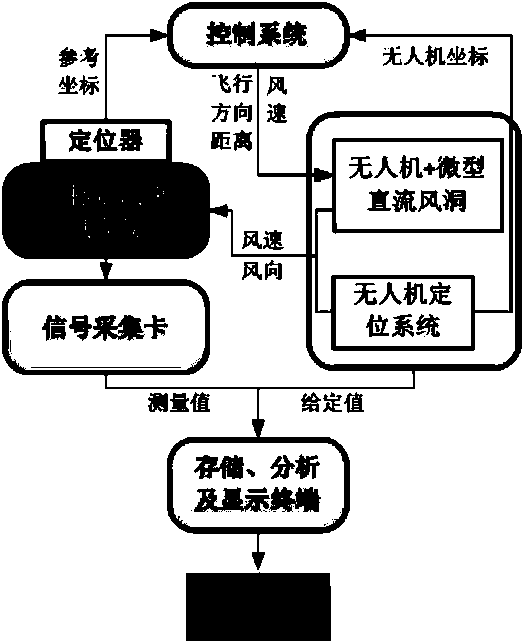
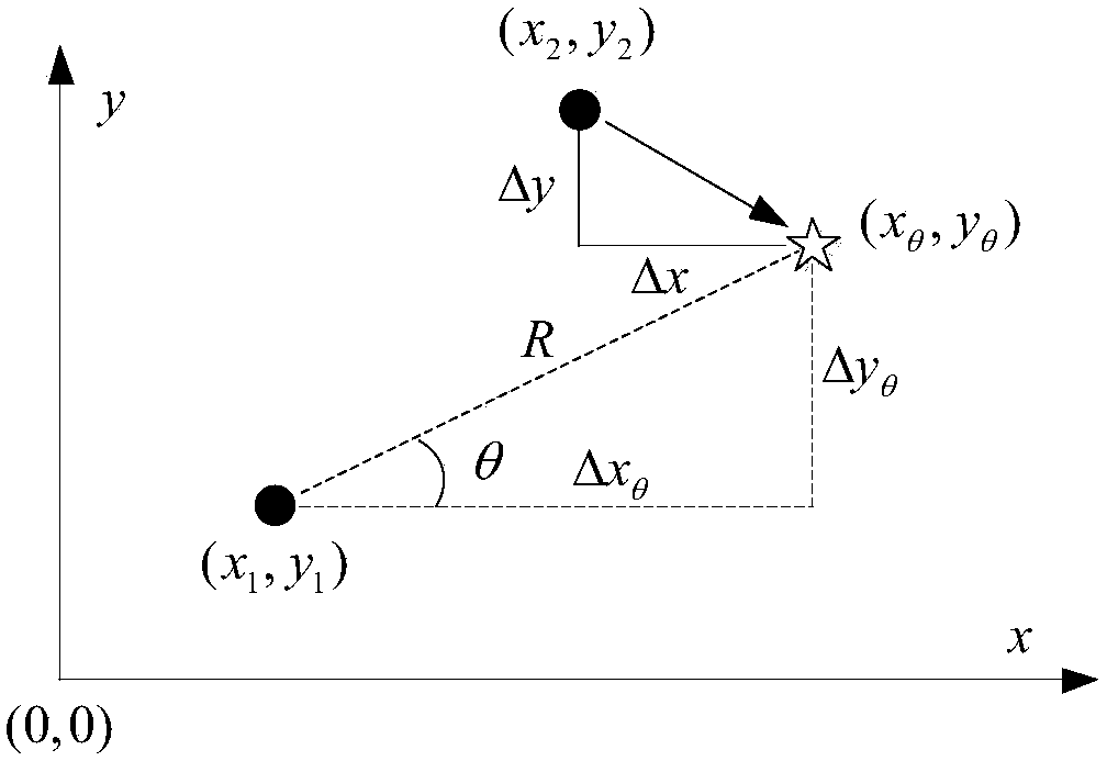

Image

  • Anemorumbometer field calibration system and method based on unmanned aerial vehicle technology
  • Anemorumbometer field calibration system and method based on unmanned aerial vehicle technology
  • Anemorumbometer field calibration system and method based on unmanned aerial vehicle technology

Examples


Embodiment Construction

[0038] The embodiments of the present invention will be described in detail below with reference to the accompanying drawings, but the present invention can be implemented in various ways defined and covered by the claims.

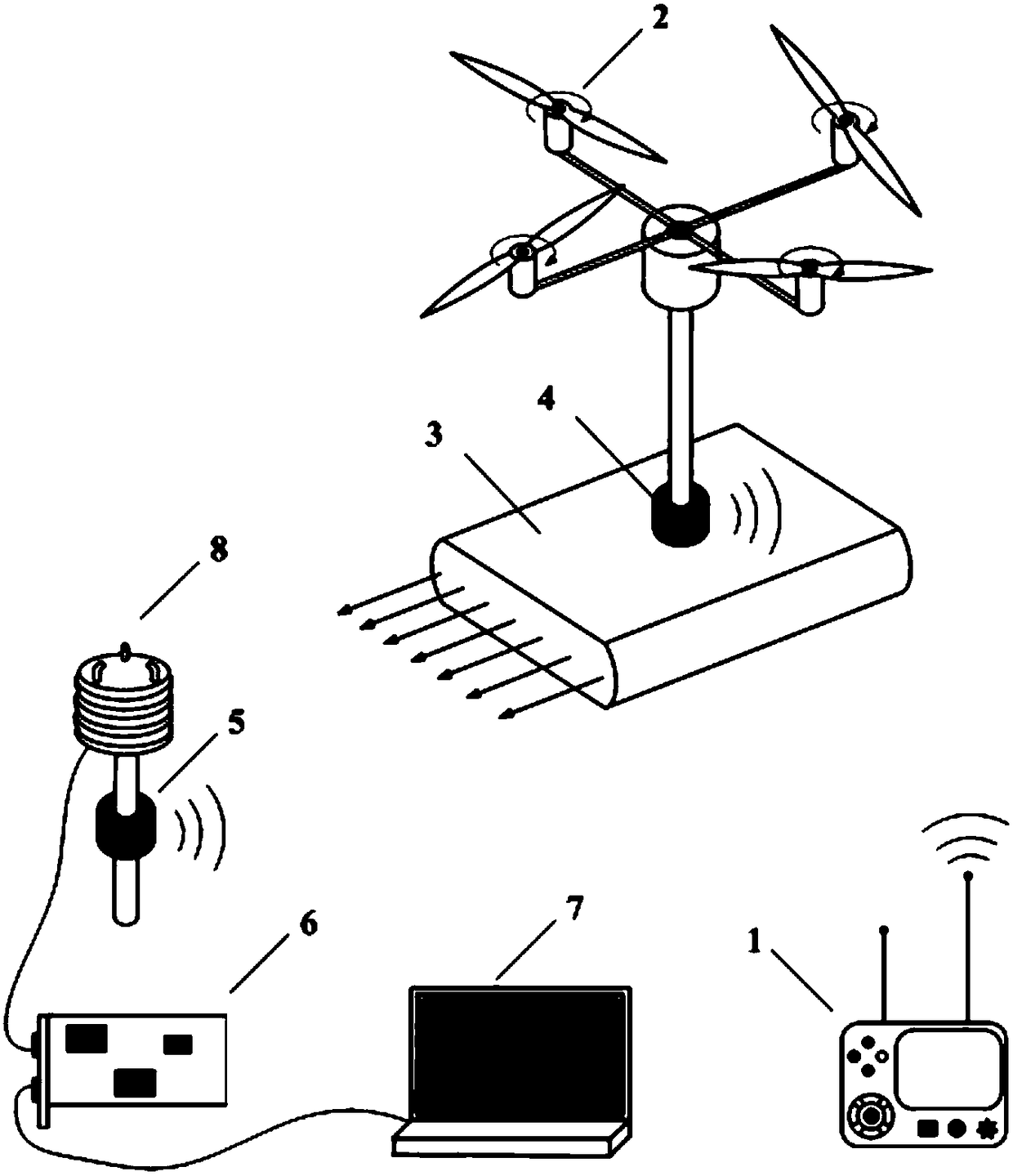
[0039] see figure 1 , an on-site calibration system for anemometers based on UAV technology, including:

[0040]The anemometer 8 to be calibrated, the first locator 5 is installed directly above or directly below it, and the anemometer 8 to be calibrated is provided with a signal output terminal;

[0041] UAV 2, the second locator 4 is installed directly below it, and the bottom of the second locator 4 is connected to the miniature DC wind tunnel 3 with the air outlet facing the anemometer 8 to be calibrated;

[0042] Acquisition card 6, it is connected with signal output end, is used for recording the electrical signal of anemometer 8 to be calibrated and sends to notebook computer 7 and carries out storage analysis and display; And

[0043] The control...


PUM


Abstract

The invention provides an anemorumbometer field calibration system and method based on an unmanned aerial vehicle technology. The system is mainly composed of a control system, an unmanned aerial vehicle (a second locator is accordingly arranged), a micro straight-flow wind tunnel, a to-be-calibrated anemorumbometer (a first locator is accordingly arranged), an acquisition card and a notebook computer. The anemorumbometer field calibration system is applicable to field calibration on an anemorumbometer of a natural disaster monitoring system along G-series high-speed railways and in use. Before the anemorumbometer field calibration system is provided, the anemorumbometer of the natural disaster monitoring system along the G-series high-speed railways only can be calibrated after being torndown and taken back to a laboratory, the process is complex in operation flow, both time and energy are consumed, efficiency is extremely low, and damage of an instrument can be easily caused in a dismounting process. The anemorumbometer field calibration system provided by the invention solves the problem of field calibration of the anemorumbometer and can be applied to the field calibration ofvarious anemorumbometers in service; and calibration operation of the anemorumbometer can be completed at relatively high efficiency and relatively low economic cost without influencing normal serviceof the instrument, no instrument is dismounted or mounted in the whole process, and security threat faced by an operator and the instrument is avoided.

Description

technical field [0001] The invention relates to the technical field of on-site calibration of anemometers, in particular to an on-site calibration system and method for anemometers based on unmanned aerial vehicle technology. Background technique [0002] In recent years, my country's high-speed railway construction has achieved world-renowned achievements. However, with the further extension of the high-speed railway network, high-speed trains are facing threats from various harsh wind environments. Due to the fast running speed of the train, the requirements for its own stability are extremely high, and the horizontal load generated by the strong wind can easily lead to traffic safety accidents. In order to avoid high-speed rail accidents caused by strong winds, the railway department installed wind speed and direction instruments along the high-speed rail to monitor the wind speed and direction along the line in real time. When the wind speed is greater than a certain lim...

Claims


Application Information

Patent Timeline
IPC IPC(8): G01P21/00G01P21/02
CPCG01P21/00G01P21/025
Inventor 敬海泉何旭辉周宇秦成文
Owner CENT SOUTH UNIV
Learn More