[0036] In order to make the objectives, technical solutions and advantages of the present invention clearer, the following further describes the present invention in detail with reference to the accompanying drawings and embodiments. It should be understood that the specific embodiments described here are only used to explain the present invention, but not to limit the present invention.
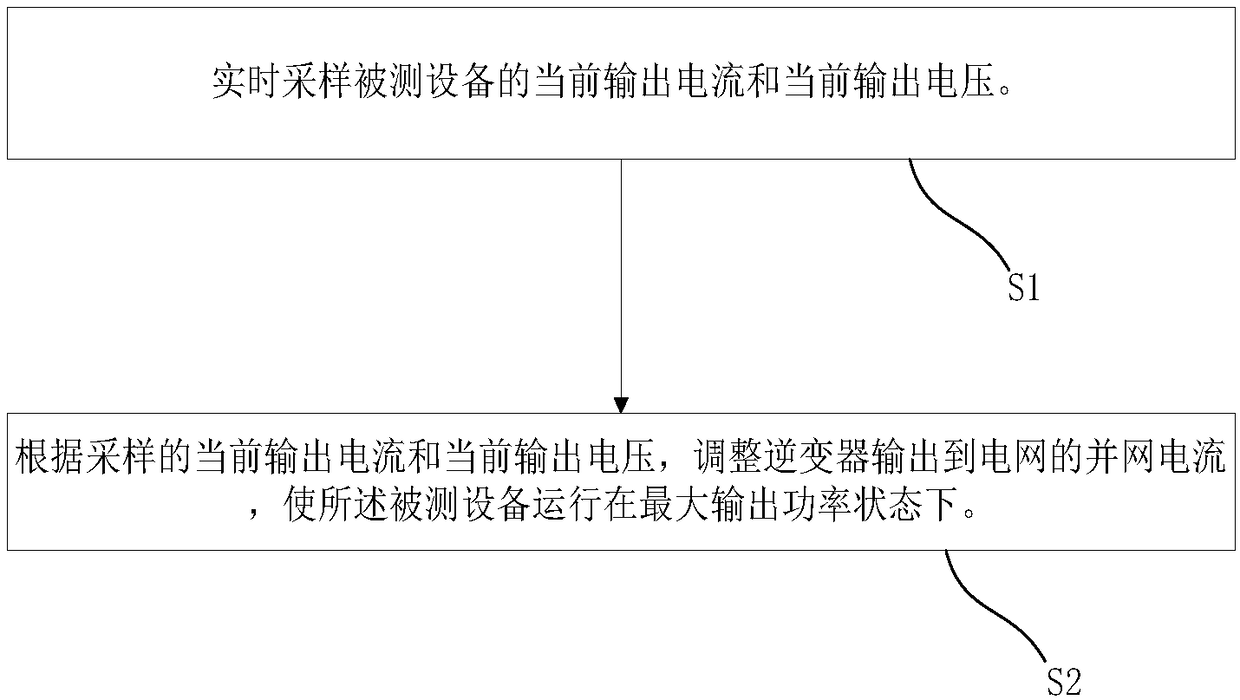
[0037] In one embodiment, such as figure 1 As shown, a feeder type inverter power supply control method includes the following steps:
[0038] S1: Real-time sampling of the current output current and current output voltage of the device under test;
[0039] S2: Adjust the grid-connected current output by the inverter to the power grid according to the sampled current output current and current output voltage, so that the device under test runs at the maximum output power state.
[0040] Further, step S1 also includes the following steps:
[0041] S11: Calculate the current output power of the device under test according to the current output voltage and current output current;
[0042] S12: Adjust the given value of the DC voltage outer loop according to the current output power;
[0043] S13: Adjust the grid-connected current inner loop given value according to the output of the DC voltage outer loop to adjust the grid-connected current output by the inverter to the grid.
[0044] Further, in the step S12, adjusting the given value of the DC voltage outer loop through the disturbance signal output by the maximum power tracking controller, and the step S12 includes:
[0045] S121: Compare the current output power of the device under test with the output power at the previous moment, and when the current output power is greater than the output power at the previous moment, step S122 is executed, and the current output power is less than the output power at the previous moment. , Go to step S123, the current output power is equal to the output power at the previous moment, go to step S124;
[0046] S122: Reduce the disturbance signal and increase the given value of the DC voltage outer loop;
[0047] S123: Increase the disturbance signal and decrease the set value of the DC voltage outer loop;
[0048] S124: The disturbance signal is 0, and the set value of the DC voltage outer loop remains unchanged.
[0049] Specifically, when the disturbance signal is a disturbance voltage, the magnitude of the disturbance voltage is controlled according to the change trend of the current output power of the device under test, and then the maximum output power of the device under test in the feedback aging mode is tracked and controlled.
[0050] Further, the sum of the given value of the DC voltage outer loop and the disturbance signal is equal to the current output voltage; the disturbance signal is greater than or equal to 0 and less than or equal to a preset value, and the initial value of the disturbance signal is the preset value; The adjustment step size of the disturbance signal is N.
[0051] Further, the step S13 includes:
[0052] S131: When the given value of the DC voltage outer loop increases or decreases, execute step S132, and when the given value of the DC voltage outer loop does not change, execute step S133;
[0053] S132: The given value of the grid-connected current inner loop keeps increasing;
[0054] S133: The set value of the grid-connected current inner loop remains unchanged.
[0055] Further, as figure 2 Shown is the voltage-power output curve of the device under test, where O is the origin of the coordinate, Pmax is the maximum output power point of the device under test, there are three characteristic points in the voltage-power output curve, the coordinates are (A, P max ), (B, P max ) And (C, Pc), the working state of the device under test can be divided into three areas: OA, AB, and BC. The output voltage of the device under test is a constant current zone between OA, and the output voltage of the device under test is between AB In the constant power zone, the output voltage of the device under test is the reduced power zone between BC, where Pc is the output power of the device under test in the reduced power zone. When the device under test works in the constant current zone, the maximum output current is constant, and the power increases with the increase of the output voltage; when the device under test works in the constant power zone, the output current decreases with the increase of the output voltage, and the output The power remains unchanged; when the device under test works in the reduced power zone, the output power decreases with the increase of the output voltage, that is, when the output voltage range of the device under test is between AB, the output power of the device under test is the maximum, which is P max. The output characteristic curve of various high-power power supplies, chargers, storage batteries and other aging test objects is generally divided into three working areas: constant current area, constant power area and power reduction area. The output power curve is unique. The maximum power point tracking of the present invention The control method is based on the working area characteristics of the above-mentioned output power curve to complete the tracking control of the maximum power point of the device under test.
[0056] The feeder-type inverter power supply control method of the present invention can adapt to various different power sources without understanding the parameters and characteristics of the tested equipment, and does not need to set the operating parameters of the tested equipment, thereby reducing the impact caused by changes in the tested equipment. The operation complexity brought about avoids the malpractice caused by improper setting of parameters.
[0057] In order to facilitate a better understanding of the above-mentioned feeder-type inverter power supply control method, a detailed explanation will be given below in conjunction with a feeder-type inverter power supply control device having the functions of the above method.
[0058] Such as image 3 As shown, a feeder type inverter power supply control device includes a maximum power point tracking module, a DC voltage outer loop, a grid-connected current inner loop, and an inverter.
[0059] The maximum power point tracking module is used to calculate the current output power of the tested device according to the current output current and current output voltage of the tested device, and adjust the set value and disturbance voltage of the DC voltage outer loop 200 according to the current output power, Make the device under test run under the maximum output power state;
[0060] DC voltage outer loop, including ADC adopting unit, adder and PI adjustment unit, used to adjust the given value of DC voltage outer loop according to current output power;
[0061] The grid-connected current inner loop, including the ADC adopting unit, adder and PI adjustment unit, is used to adjust the given value of the grid-connected current inner loop according to the output of the DC voltage outer loop;
[0062] The grid-connected control module is used to adjust and control the grid-connected current output to the grid according to the given value of the grid-connected current inner loop.
[0063] Further, the maximum power point tracking module is used to reduce the disturbance signal and increase the given value of the DC voltage outer loop when the current output power of the device under test is on an upward trend; when the current output power of the device under test is on a downward trend Increase the disturbance signal and reduce the set value of the DC voltage outer loop; when the current output power of the device under test reaches the maximum value, the disturbance signal is zero and the set value of the DC voltage outer loop remains unchanged.
[0064] When the feeder-type inverter power supply control device is working, it collects the output voltage and output current of the equipment under test, calculates the current output power value of the equipment under test according to the sampled value, and compares and judges with the output power at the previous time, and stores The maximum output power, at the next sampling moment, the power value P calculated in real time k The maximum power value P latched with the previous sampling time k-1 To compare if P k P k-1 , That is, the current power is greater than the latched maximum power value, indicating that the power is on the rise, and the current voltage control direction is correct, then continue to control according to the voltage direction at the previous moment to reduce the disturbance signal; if P k k-1 , That is, when the current power is less than the latched maximum power value, it indicates that the current power is in a downward trend and the disturbance signal is increased; if P k =P k-1 , That is, the power at the current moment is equal to the maximum power value that is latched, indicating that the power has reached the maximum value, and the value of the disturbance signal is adjusted to 0. Finally, by automatically adjusting the size of the disturbance signal, the output power of the device under test is kept to the maximum and the aging test efficiency is improved.
[0065] Further, the sum of the given value of the DC voltage outer loop and the disturbance signal is equal to the current output voltage; the disturbance signal is greater than or equal to 0 and less than or equal to a preset value, and the initial value of the disturbance signal is the preset value; The maximum power point tracking module adjusts the step size of the disturbance signal to N.
[0066] Specifically, the disturbance signal is a disturbance voltage. When the output power of the device under test is at the maximum output power, the given value of the DC voltage outer loop is equal to the output voltage of the device under test. When the feeder-type inverter power supply control device is working, the given value of the DC voltage outer loop is stable within the set range.
[0067] Further, when the disturbance signal is greater than 0, the given value of the grid-connected current inner loop continuously increases, and when the disturbance signal is equal to 0, the magnitude of the given value of the grid-connected current inner loop remains unchanged.
[0068] The feeder-type inverter power supply control device detects the changes in the output voltage and output current of the equipment under test in real time during the work process. According to the capacity of the equipment under test, it automatically adjusts the size of the disturbance signal and adjusts the output voltage and current to make The output power of the device under test is kept to the maximum, and the efficiency of the aging test is improved to ensure that the device under test always works at the maximum power point, which effectively improves the efficiency of the device aging test.
[0069] Although the present invention has been disclosed as above in preferred embodiments, it should not be understood as a limitation to the scope of the invention. It should be pointed out that for those skilled in the art, without departing from the concept of the present invention, several modifications and improvements can be made, and these all fall within the protection scope of the present invention. Therefore, the protection scope of the present invention is subject to the scope defined by the claims.