
Smart energy demonstration zone planning method considering demand side response

A demand-side response, smart energy technology, applied in the direction of load forecasting in AC network, AC network circuit, single-network parallel feeding arrangement, etc., to reduce peak load, reduce peak-to-valley difference, and improve power supply reliability.

Inactive Publication Date: 2018-09-04
GRID POWER PLANNING & RES CENT OF GUANGDONG GRID POWER CO LTD
View PDF4 Cites 11 Cited by
  • Summary
  • Abstract
  • Description
  • Claims
  • Application Information

AI Technical Summary

Problems solved by technology

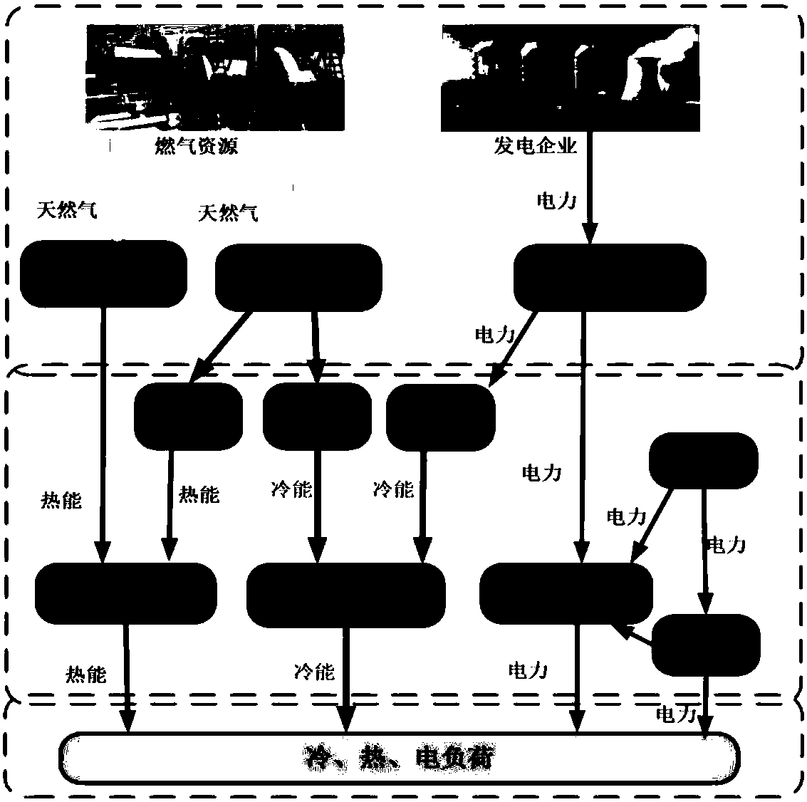
[0002] At present, smart energy areas include the production of renewable energy such as wind power and solar energy, as well as commercial and domestic applications. The traditional planning method uses separate planning and design of various energy supply systems such as power supply, gas supply, and heat supply. Research on the peak-shaving and valley-filling of the integrated energy system of electricity, but no in-depth analysis of the power-to-gas energy supply characteristics and the demand-side response mechanism of important users

Method used


Image

  • Smart energy demonstration zone planning method considering demand side response
  • Smart energy demonstration zone planning method considering demand side response
  • Smart energy demonstration zone planning method considering demand side response

Examples


Embodiment Construction

[0051] The accompanying drawings and embodiments are only for illustrative purposes and cannot be construed as limitations on this patent;

[0052]For those skilled in the art, it is understandable that some well-known structures and descriptions thereof may be omitted in the drawings.

[0053] Unless otherwise defined, all technical and scientific terms used herein have the same meaning as commonly understood by one of ordinary skill in the technical field of the invention. The terms used herein in the description of the present invention are for the purpose of describing specific embodiments only, and are not intended to limit the present invention. As used herein, the term "or / and" includes any and all combinations of one or more of the associated listed items.

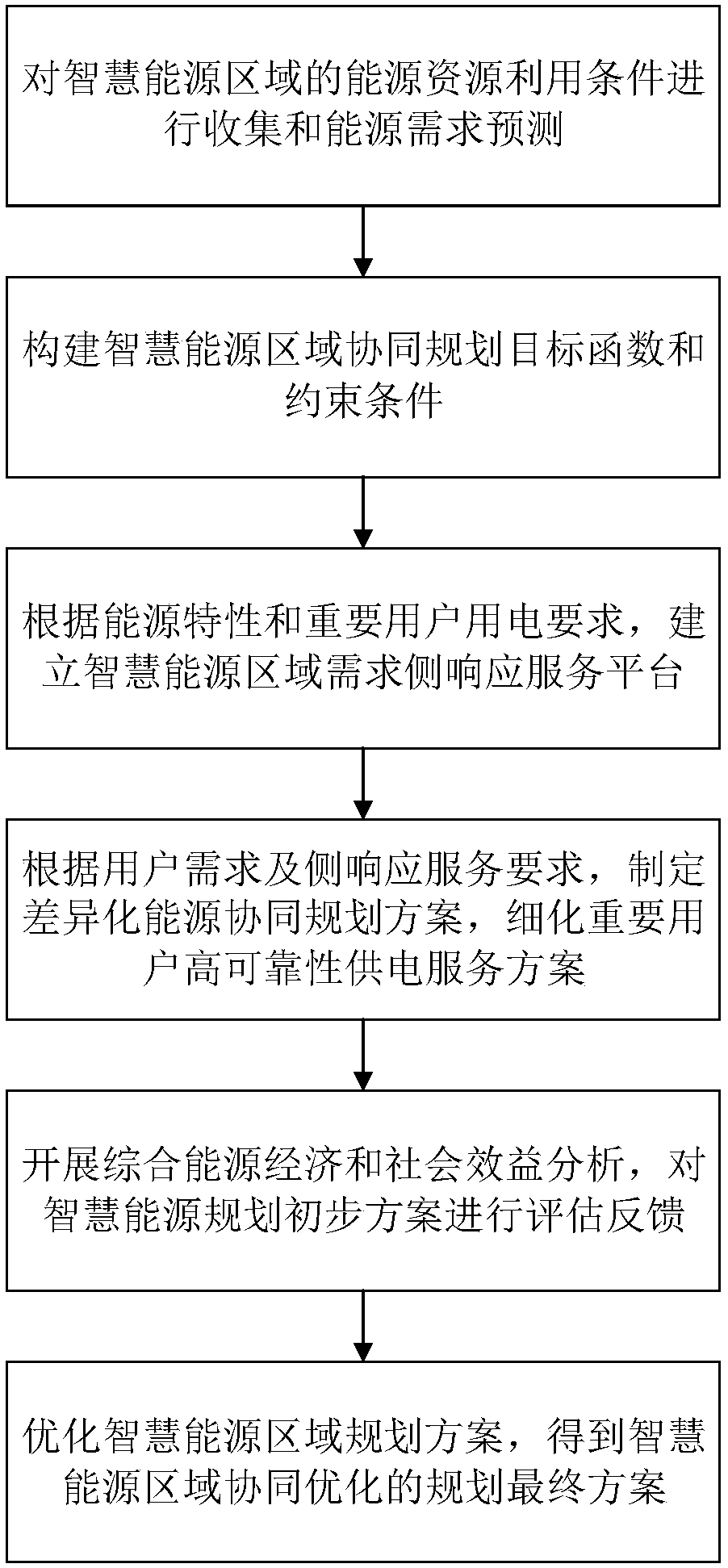
[0054] A smart energy demonstration area planning method considering demand side response, such as figure 1 shown, including the following steps:

[0055] S1. Collect energy resource utilization conditions and f...


PUM


Abstract

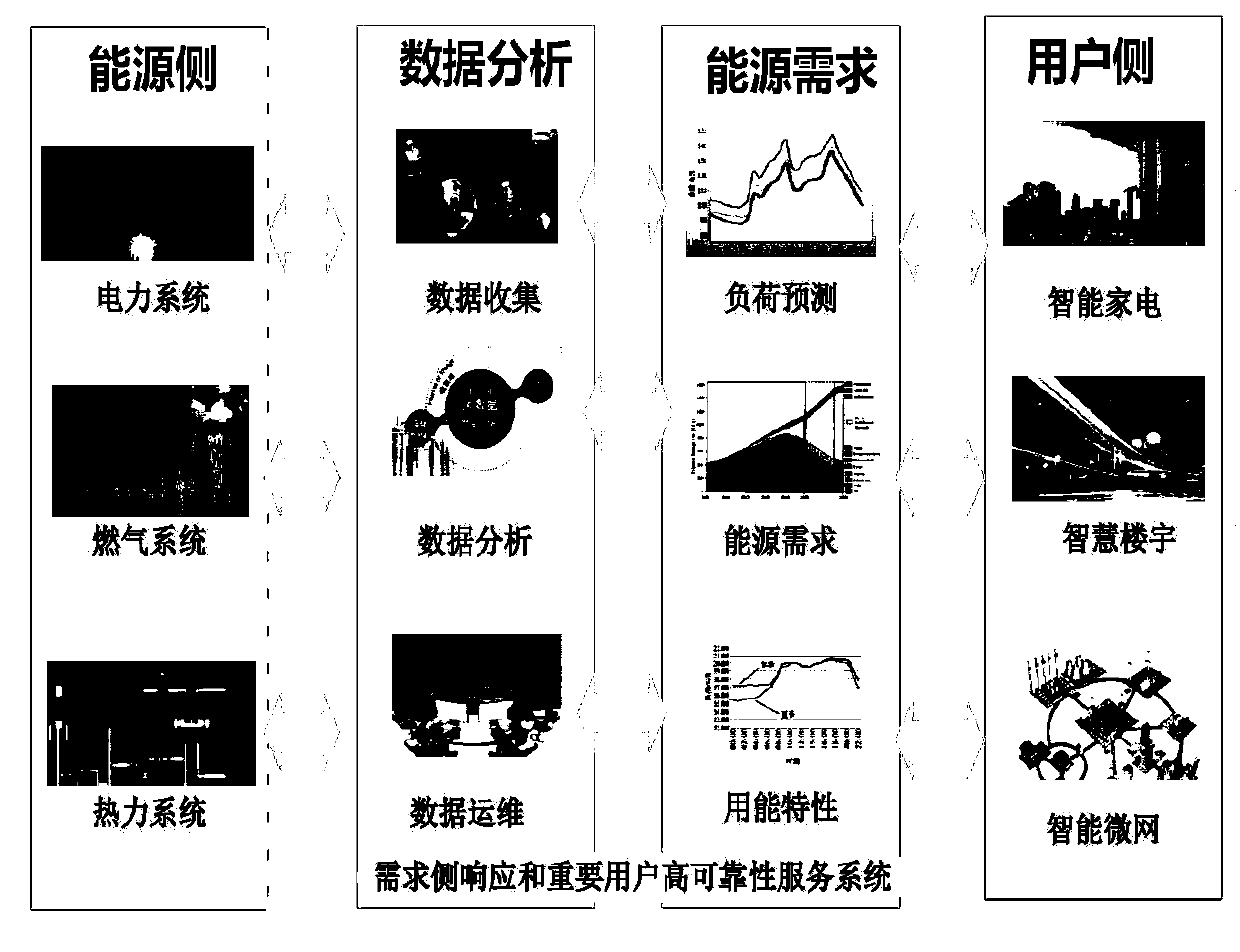
The invention discloses a smart energy demonstration zone planning method considering demand side response. The method comprises the following steps: S1, collection of energy resource utilization conditions in a smart energy zone and energy demand forecasting are carried out; S2, a smart energy zone collaborative planning objective function and constraint conditions are built; S3, according to energy characteristics and power consumption demands of important users, a smart energy zone demand side response service platform is built; S4, according to the user demands and the demand side responseservice requirements, a differentiated energy collaborative planning scheme is made; S5, an initial smart energy planning scheme is evaluated and fed back; and S6, a smart energy zone planning schemeis optimized to obtain a final smart energy zone collaborative optimized energy conservation and environment protection planning scheme. Zone energy complementation and cascade utilization can be realized, peak load of certain users is reduced and a peak valley difference is reduced, the power supply reliability and the smart energy utilization efficiency are improved, and purposes of high-efficiency demonstration zone energy utilization, information coordination and interaction, energy conservation and emission reduction and green environmental protection development can be realized.

Description

technical field [0001] The present invention relates to the field of energy planning, and more specifically, relates to a planning method for a smart energy demonstration area considering demand-side response. Background technique [0002] At present, smart energy areas include the production of renewable energy such as wind power and solar energy, as well as commercial and domestic applications. The traditional planning method uses separate planning and design of various energy supply systems such as power supply, gas supply, and heat supply. However, there is no in-depth analysis of the power-to-gas energy supply characteristics and the demand-side response mechanism of important users. Developing renewable energy such as wind power and solar energy in the smart energy demonstration zone, and increasing the efforts to promote technological change and innovation in the energy field, is of great significance for optimizing the energy field structure of the smart park and rea...

Claims


Application Information

Patent Timeline
IPC IPC(8): H02J3/46
CPCH02J3/46H02J3/003H02J2203/20
Inventor 李阳高崇余梦泽潘险险郇嘉嘉陈沛东龚贤夫
Owner GRID POWER PLANNING & RES CENT OF GUANGDONG GRID POWER CO LTD
Learn More