
Sealing element, and fuel injector comprising a sealing element

A technology for fuel injectors and sealing components, applied in fuel injection devices, fuel injection valves driven by fluid pressure, special fuel injection devices, etc., can solve problems such as increased space requirements, and achieve compact layout, cheap and highly accurate manufacturing , Improve the sealing effect

Active Publication Date: 2018-09-04
ROBERT BOSCH GMBH
View PDF9 Cites 0 Cited by
  • Summary
  • Abstract
  • Description
  • Claims
  • Application Information

AI Technical Summary

Problems solved by technology

In this sealing element, therefore, an increased space requirement is also required with regard to the assembly consisting of structural element and sealing element

Method used


Image

  • Sealing element, and fuel injector comprising a sealing element
  • Sealing element, and fuel injector comprising a sealing element
  • Sealing element, and fuel injector comprising a sealing element

Examples


Embodiment Construction

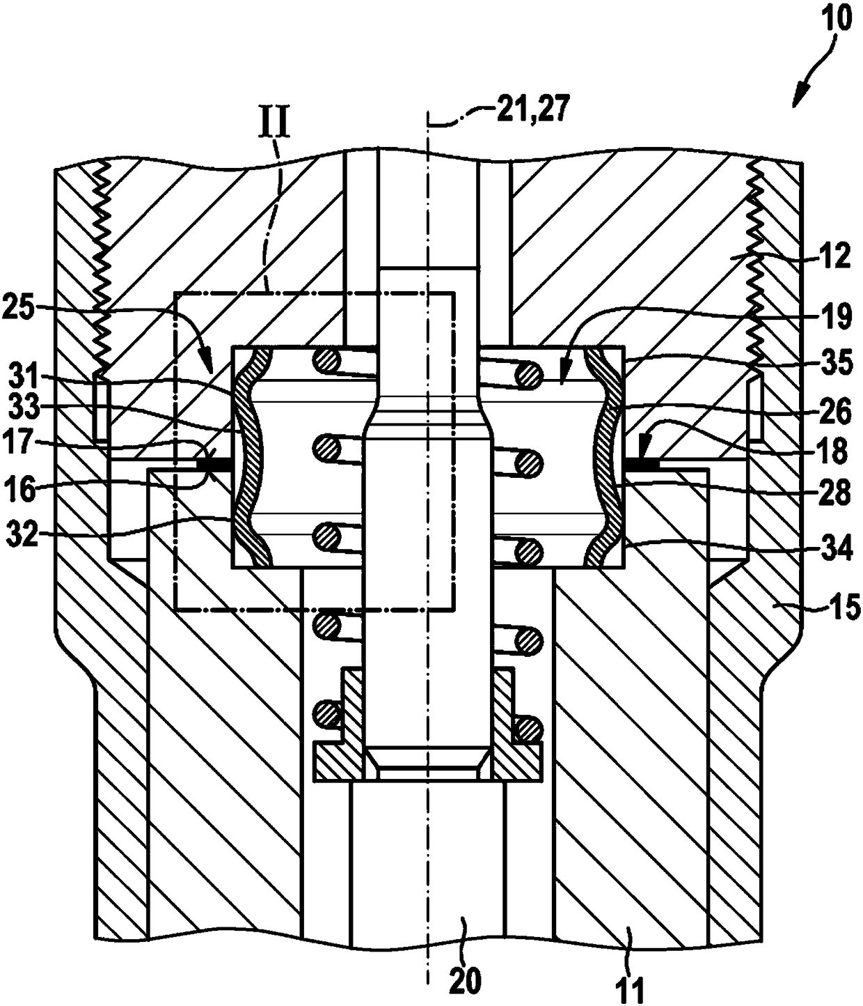
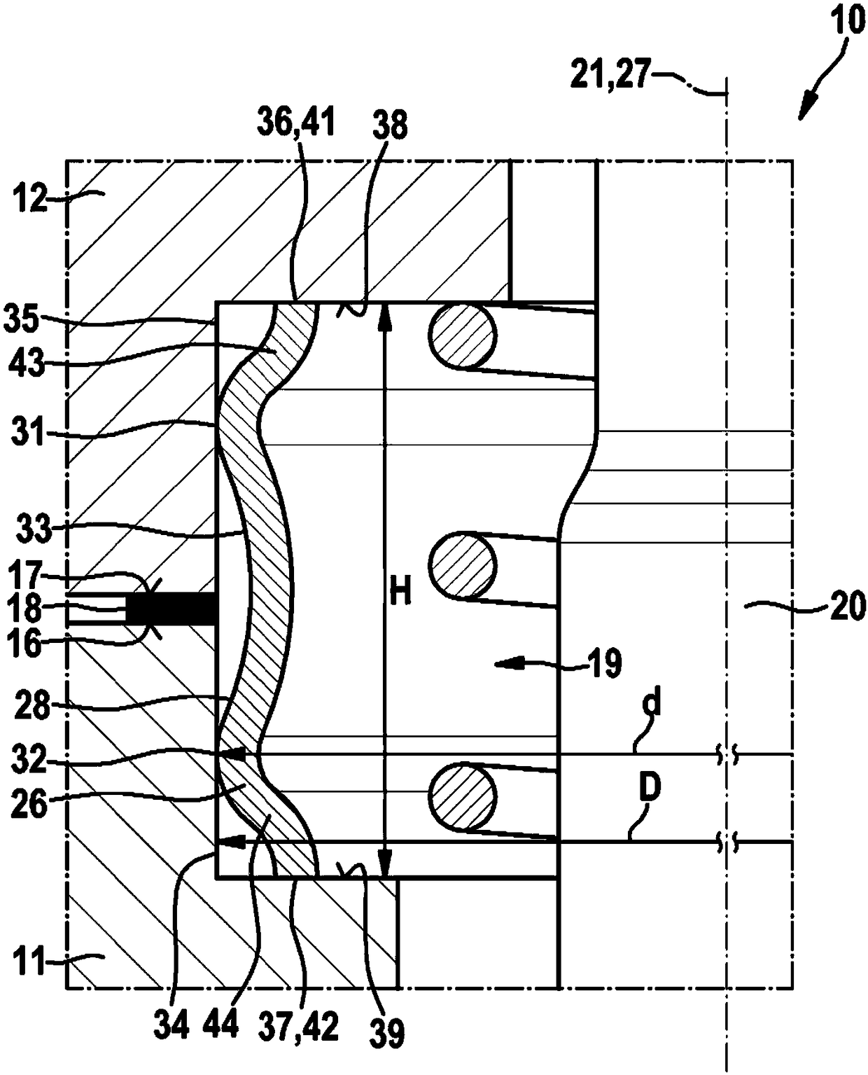
[0021] exist figure 1 A fuel injector 10 such as that shown in the center is used to inject fuel into a combustion chamber (not shown) of a compression ignition internal combustion engine. Fuel injector 10 is in particular designed as a so-called common rail injector.

[0022] The fuel injector 10 has a nozzle body 11 , to which a holding body 12 adjoins in the direction opposite to an injection opening (not shown) of the nozzle body 11 . The nozzle body 11 and the holder body 12 are axially clamped by means of a nozzle clamping nut 15 . In particular, the nozzle body 11 and the holding body 12 are arranged in at least regional contact with each other in the region of the opposite end faces 16 , 17 in the installed state. exist figure 1 and 2 In the exemplary embodiment shown, it is ensured by corresponding machining of the end faces 16 , 17 that, in the state of the nozzle body 11 mounted axially on the holding body 12 , the two end faces 16 , 17 at least in the radially ...


PUM


Abstract

The invention relates to a sealing element (26; 26a) for a high-pressure connection (25) in a fuel injector (10; 10a); said sealing element (26; 26a) is in the form of a sleeve and includes, on the outer circumference thereof, a radially outward-protruding first sealing zone (31, 32) designed to rest against a part (11, 12). According to the invention, at least two first sealing zones (31, 32) areprovided which are axially located at a distance from one another in relation to a longitudinal axis (27) of the sealing element (26; 26a).

Description

technical field [0001] The invention relates to a sealing element for a high-pressure connection in a fuel injector according to the preamble of claim 1 . Furthermore, the invention relates to a fuel injector using a sealing element according to the invention. Background technique [0002] A sealing element according to the preamble of claim 1 is known from DE 10 2012 222 167 A1 of the applicant. With the known sealing element, the high-pressure line leading to the connecting piece in the fuel injector can be sealed. In this case, the high-pressure line and the connecting piece are axially clamped together by means of a union nut, wherein the sealing element is arranged in bores of two axially spaced components (high-pressure line and connecting piece) spaced apart from one another. When the high-pressure line is axially clamped to the connecting piece, the sealing element is deformed radially outward and bears with its outer side or outer periphery against the mouth regio...

Claims


Application Information

Patent Timeline
IPC IPC(8): F02M55/00
CPCF02M55/005F02M55/008F02M2200/26F02M2547/003
Inventor S·莱泽尔
Owner ROBERT BOSCH GMBH
Learn More