Novel test tube rack
A test tube rack, a new type of technology, applied in the direction of test tube holders/clamps, etc., can solve the problems of poor adaptability of test tubes, and achieve the effect of widening types and satisfying fixation
- Summary
- Abstract
- Description
- Claims
- Application Information
AI Technical Summary
Problems solved by technology
Method used
Image

Examples
no. 1 example
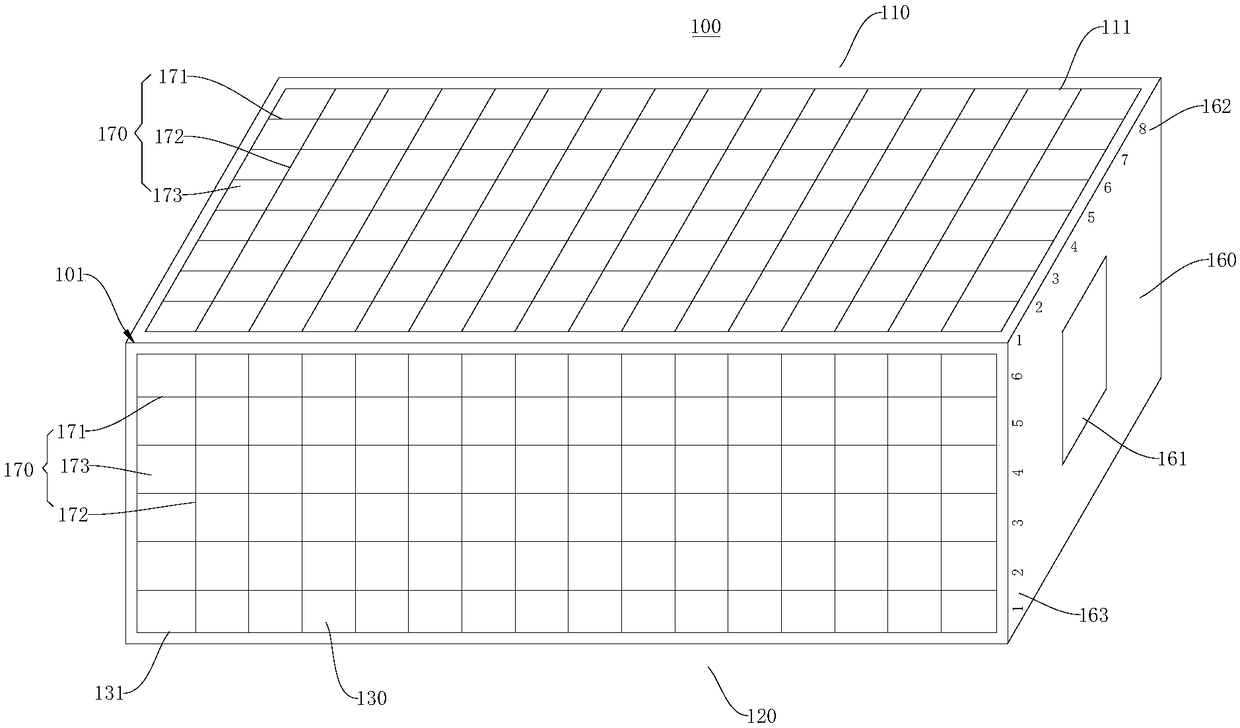
[0034] Please also refer to figure 1 and figure 2 , this embodiment provides a new type of test tube rack 100 , which includes a fixing bracket 101 . The fixing bracket 101 has a roughly rectangular parallelepiped structure, which includes a bracket top 110 , a bracket bottom 120 and a bracket side wall connected between the bracket top 110 and the bracket bottom 120 .
[0035] Please also refer to figure 1 , figure 2 , image 3 and Figure 4 , the bracket side wall includes a first side wall 130, a second side wall 140, a third side wall 150 and a fourth side wall 160 connected in sequence, the first side wall 130 is set opposite to the third side wall 150, and the second side wall 140 is disposed opposite to the fourth side wall 160 , and the second opening 131 is disposed on the first side wall 130 .
[0036] The above arrangement of the fixed bracket 101 ensures the stability of the test tube rack structure. Each surface of the support top 110 , the support bottom...
no. 2 example
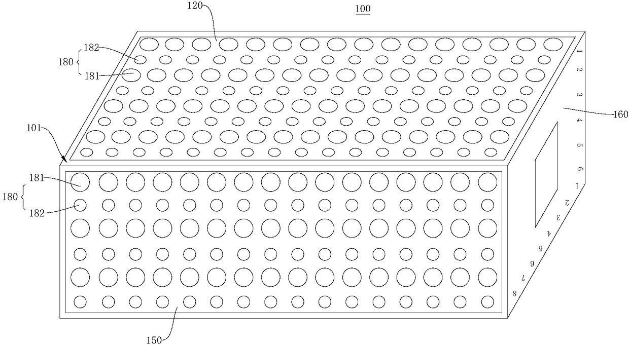
[0065] This embodiment provides a new type of test tube rack, which differs from the new type of test tube rack 100 provided in the first embodiment in that: the bottom 120 of the rack and the third side wall 150 are not provided with the second test tube fixing unit 180 . Both the bracket bottom 120 and the third side wall 150 are provided with a second opening 131 communicating with the cavity inside the fixing bracket 101 , and the second opening 131 is provided with the first test tube fixing unit 170 .
no. 3 example
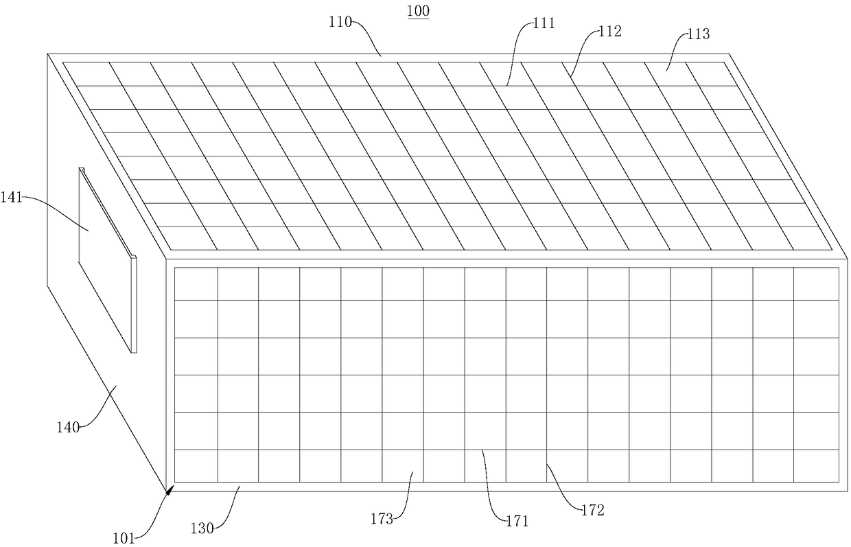
[0067] This embodiment provides a new type of test tube rack, which is different from the new type of test tube rack provided by the second embodiment in that: the second side wall 140 is not provided with a label slot 141 , and the fourth side wall 160 is not provided with an identification component. Both the second sidewall 140 and the fourth sidewall 160 are provided with a cavity communicating with the inside of the fixing bracket 101 and a second opening 131 , and the first test tube fixing unit 170 is arranged at the second opening 131 .
[0068] To sum up, in the novel test tube rack provided by the present invention, the fixed bracket ensures the stability of the test tube rack. The first elastic part and the second elastic part of the first test tube fixing unit encircle the cavity for clamping the test tube. Since the first elastic part and the second elastic part are elastic and can be stretched, the size of the cavity can be adjusted according to different models. ...
PUM
 Abstract
Description
Claims
Application Information
 - R&D
- Intellectual Property
- Life Sciences
- Materials
- Tech Scout
- Unparalleled Data Quality
- Higher Quality Content
- 60% Fewer Hallucinations
Browse by: Latest US Patents, China's latest patents, Technical Efficacy Thesaurus, Application Domain, Technology Topic, Popular Technical Reports.
© 2025 PatSnap. All rights reserved.Legal|Privacy policy|Modern Slavery Act Transparency Statement|Sitemap|About US| Contact US: help@patsnap.com