Rapid prototyping mold manufacturing device

A mold manufacturing and prototyping technology, which is applied in the field of rapid prototyping mold manufacturing devices, can solve the problems of low quality, low efficiency, and easy deviation, and achieve the effects of accurate punching position, simple and convenient operation structure, and improved stability.

Inactive Publication Date: 2018-09-07
广州峥航机械设备有限公司
View PDF6 Cites 0 Cited by
  • Summary
  • Abstract
  • Description
  • Claims
  • Application Information

AI Technical Summary

Problems solved by technology

The design and manufacture of the mold is very important, and the mold itself is composed of different parts and metal plates. The current punching of metal plates is carried out by hand-held punching guns, which is easy to miss, low in efficiency and low in quality.

Method used


Image

  • Rapid prototyping mold manufacturing device
  • Rapid prototyping mold manufacturing device
  • Rapid prototyping mold manufacturing device

Examples


Embodiment Construction

[0017] The preferred embodiments of the present invention will be described in detail below in conjunction with the accompanying drawings, so that the advantages and features of the present invention can be more easily understood by those skilled in the art, so as to define the protection scope of the present invention more clearly.

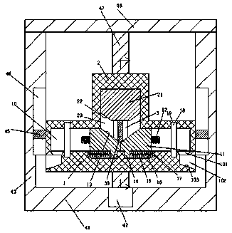
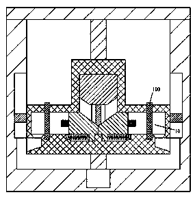
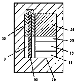
[0018] refer to Figure 1-5 A rapid prototype mold manufacturing device shown includes a base 1 and a top seat 2 arranged on the top of the base 1 , the rear side wall of the base 1 is provided with a lifting screw 47 up and down, and the lifting screw The bottom of the rod 47 is dynamically connected with the lifting motor 42. The lifting motor 42 is embedded in the bottom plate 41. The top end of the bottom plate 41 is fixedly arranged with a support plate 43, and the inner surface of the support plate 43 is provided with a lifting guide. Groove 41, the left and right sides of the base 1 are commensurate with fixed lifting guide blocks 45, the ...


PUM


Abstract

The invention discloses a rapid prototyping mold manufacturing device. The rapid prototyping mold manufacturing device comprises a base seat and a top seat, wherein the top seat is arranged at the topof the base seat. An ascending-and-descending spiral rod is arranged on the side wall of the base seat in a vertically-through manner. The bottom of the ascending-and-descending spiral rod is in power connection with an ascending-and-descending motor in a matched manner. The ascending-and-descending motor is arranged in a base plate in an embedded manner. Support plates are fixedly arranged on the top end face of the base plate in a manner that the support plates are symmetrical in the left-right direction. The inner side face of each support plate is provided with an ascending-and-descendingguiding groove. Ascending-and-descending guiding blocks are fixedly arranged on the left side face and the right side face of the base seat in a manner that the ascending-and-descending guiding blocks are symmetrical in the left-right direction. Each ascending-and-descending guiding block is connected with the corresponding ascending-and-descending guiding groove in a sliding and matched manner.A top plate is fixedly arranged at the tops of the support plates. The top end of the ascending-and-descending spiral rod is rotatably connected with the top plate in a matched manner. The rapid prototyping mold manufacturing device is simple in structure and convenient to operate; punching operation machining can be conducted on two panels at the same time; work efficiency of stamping and punching of the panels is greatly improved; time and labor are saved; punching positions of the metal panels are precise; and manufacturing efficiency of a prototyping mold is effectively improved.

Description

technical field [0001] The invention relates to the field of industrial manufacturing, in particular to a rapid prototype mold manufacturing device. Background technique [0002] Molds are various molds and tools used in industrial production for injection molding, blow molding, extrusion, die-casting or forging forming, smelting, stamping and other methods to obtain the required products. The design and manufacture of the mold is very important, and the mold itself is composed of different parts and metal plates. The current punching of metal plates is carried out by manual hand-held punching guns, which is easy to miss, low in efficiency and low in quality. Contents of the invention [0003] The technical problem to be solved by the present invention is to provide a rapid prototype mold manufacturing device, which can solve the above-mentioned problems in the prior art. [0004] In order to solve the above problems, the present invention adopts the following technical s...

Claims


Application Information

Patent Timeline
Patent Type & Authority Applications(China)
IPC IPC(8): B21D28/26
CPCB21D28/002B21D28/26
Inventor 韦红生
Owner 广州峥航机械设备有限公司
Why Eureka
Try Eureka