
Photoelectric positioner for transportmanipulator and positioning method thereof

A technology of positioner and manipulator, which is applied to conveyor objects, transportation and packaging, etc., can solve the problems of shortened service life, inconvenient use, no protective measures, etc., to enhance cold and heat resistance, facilitate transmission of information, and prolong service life. Effect

Active Publication Date: 2018-09-07
南理工泰兴智能制造研究院有限公司
View PDF5 Cites 2 Cited by
  • Summary
  • Abstract
  • Description
  • Claims
  • Application Information

AI Technical Summary

Problems solved by technology

[0003] The photoelectric locator used in the prior art handling manipulator has the following problems: 1. The information transmission between the existing photoelectric locators is mostly connected through signal lines, and the installation process is complicated and cumbersome, resulting in inconvenience in use; Most of the photoelectric locators only have one set. A single set of photoelectric locators locates the handling manipulator for a long time. The internal processing components work too hard, which is easy to shorten their service life, frequent maintenance and replacement, and increase maintenance costs; 3. Some handling manipulators will vibrate during the handling process, which will drive the photoelectric positioner to fluctuate, which will easily affect the measurement results of the photoelectric positioner. However, there are no relevant protective measures for the existing photoelectric positioner for handling manipulators.

Method used


Image

  • Photoelectric positioner for transportmanipulator and positioning method thereof
  • Photoelectric positioner for transportmanipulator and positioning method thereof
  • Photoelectric positioner for transportmanipulator and positioning method thereof

Examples


Embodiment 1

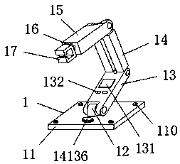
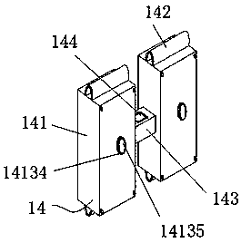
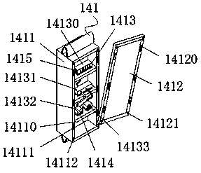
[0040] see Figure 1-4 , the present invention provides the following technical solutions: a photoelectric positioner for a transport manipulator and its positioning method, comprising a transport manipulator body 1, a fixed seat 11, a rotating shaft 12, a first rotating arm 13, a photoelectric positioning mechanism 14, and a second rotating arm 15 , the transmission part 16 and the manipulator 17, the handling manipulator body 1 includes a fixed seat 11, a rotating shaft 12, a first arm 13, a photoelectric positioning mechanism 14, a second arm 15, a transmission part 16 and a manipulator 17, wherein the fixed seat 11 The first rotating arm 13 is arranged above, and the fixed seat 11 is connected with the first rotating arm 13 through the rotating shaft 12. The side of the transport manipulator body 1 away from the fixed seat 11 is provided with a photoelectric positioning mechanism 14, and the photoelectric positioning mechanism 14 is far away from the first rotating arm 13. ...


PUM


Abstract

The invention discloses a photoelectric positioner for a transport manipulator. The photoelectric positioner for the transport manipulator comprises a transport manipulator body, a fixing seat, a rotating shaft, a first rotating arm, a photoelectric positioning mechanism, a second rotating arm, a transmission piece and a manipulator. The transport manipulator body comprises the fixing seat, the rotating shaft and the first rotating arm. A first photoelectric sensor and a second photoelectric sensor are correspondingly mounted on the surfaces of the X axis and the Y axis of the transport manipulator body,the change of light sources can be measured in real time, andmeasured signals are transmitted to a micro processer after being treated by a signal receiver; the signals are transmitted to adisplay screen by a signal projector after being transferred and treated by the micro processer; finally, related operationis performed by the staff through controlling function keys. Data transmission between the signal projector and the display screen is carried out through wirelessradio frequency signals so that position information of the transport manipulator can be collected rapidly and circuit connection between the signal projector and the display screen is omitted; the information transmission is convenient and the using effect is good.

Description

technical field [0001] The invention belongs to the technical field of photoelectric positioning of construction manipulators, and in particular relates to a photoelectric positioner for a transport manipulator and a positioning method thereof. Background technique [0002] The construction manipulator is a new type of mechanical equipment for the modern construction of large-scale underground projects. It can not only improve the quality of pipeline construction, but also ensure the quality of pipeline construction. The frequency of use is very high, and the photoelectric positioner is an important part of the operation of the handling manipulator. The function of the hand photoelectric locator is being perfected day by day, but there are still some deficiencies to be improved. [0003] The photoelectric locator used in the prior art handling manipulator has the following problems: 1. The information transmission between the existing photoelectric locators is mostly connect...

Claims


Application Information

Patent Timeline
Patent Type & Authority Applications(China)
IPC IPC(8): B65G47/90
CPCB65G47/90
Inventor 吴东
Owner 南理工泰兴智能制造研究院有限公司
Learn More