

Liftable fan based on stainless steel impeller
A stainless steel, impeller technology, applied in the components of the pumping device for elastic fluid, mechanical equipment, machine/engine, etc. The amount of sieving and the effect of increasing the surface area
- Summary
- Abstract
- Description
- Claims
- Application Information
AI Technical Summary
Problems solved by technology
Method used
Image

Examples
Embodiment 1
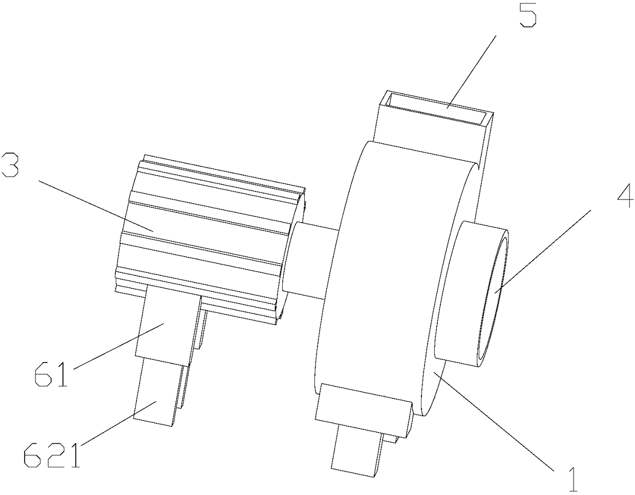
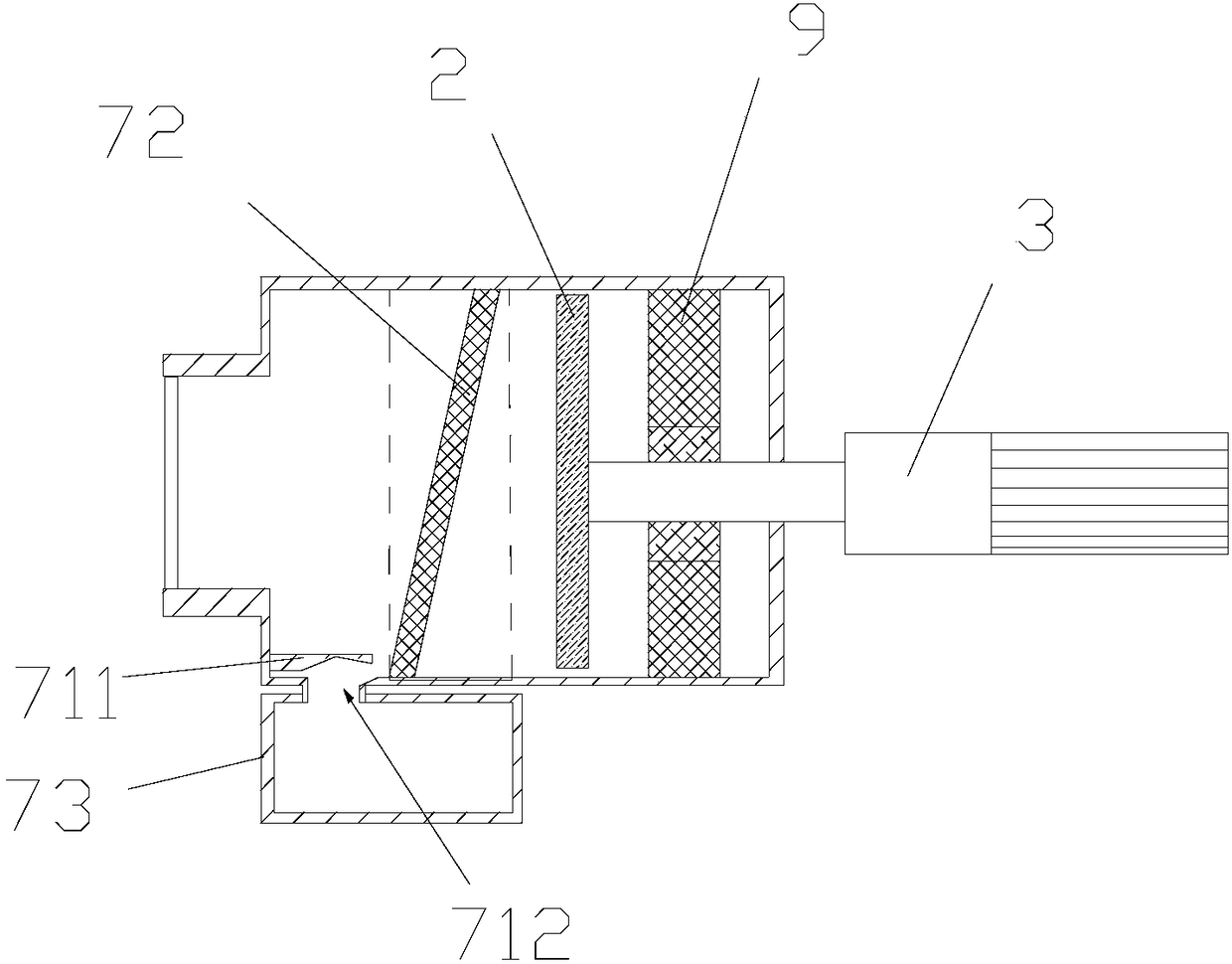
[0064] Such as figure 1 , 2 As shown, this embodiment discloses a liftable fan based on a stainless steel impeller, including a housing 1, an impeller 2, and a motor 3. The motor 3 is connected to the impeller 2, and the impeller 2 is limited in the inner cavity of the housing 1. The casing 1 is provided with an air inlet 4 and an air outlet 5 . Both the air inlet 4 and the air outlet 5 are provided with grilles.
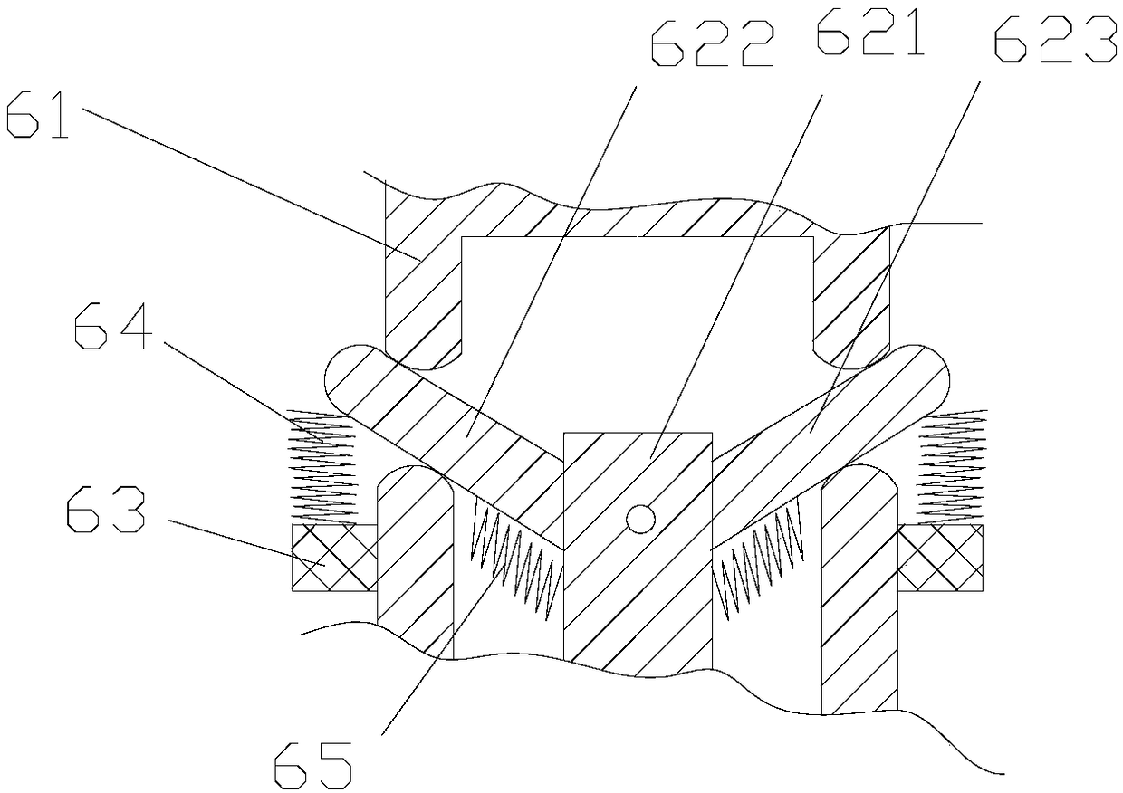
[0065] Such as figure 1 , 3 , Shown in 4, at the bottom of housing 1, the bottom of motor 3 are all provided with elevating type feet, elevating type feet include straight tube 61, lengthen support bar, support block 63, support spring 64. The straight cylinder 61 is vertically arranged, and its side is provided with a through hole that penetrates the straight cylinder 61 in the radial direction. Several through holes are spaced apart from top to bottom, and several support blocks 63 are symmetrically fixed on the side of the straight cylinder 61 and located bel...
Embodiment 2
[0075] Such as Figure 9-11 As shown, the difference between this embodiment and the above embodiments is that the impeller 2 includes an upper cover plate 21 , a lower cover plate 22 , blades 23 , and a shaft sleeve 24 . The blades 23 are welded on the corresponding cover plate, specifically the upper cover plate 21 or the lower cover plate 22 . The upper cover plate 21 is covered with the lower cover plate 22 , and the shaft sleeve 24 is installed in the center of the lower cover plate 22 or the upper cover plate 21 . The upper cover plate 21, the lower cover plate 22, the blades 23, and the shaft sleeve 24 are all made of SUS304 stainless steel. In addition, other prior art impellers should also fall within the protection scope of the present invention.
Embodiment 3
[0077] Such as Figure 5-7 As shown, the difference between this embodiment and the above-mentioned embodiment is that: the left and right ends of the inner top wall of the inner cavity of the housing 1 are respectively suspended with a third spring 8, and the top of the frame 71 can be connected with the third spring 8. touch. Such as Figure 12 As shown, the sawtooth surface of the rack 74 includes sawtooth distributed from top to bottom in the middle area and non-rack 74 areas on both sides, and a rubber strip 710 is installed on the non-rack 74 area, and the rubber strip 710 can be connected with the housing 1 contact with the inner walls of the internal cavity. In some embodiments, the smooth surface of the rack 74 may also be fitted with a rubber strip.
[0078] The present invention suspends the third spring 8 at the left and right ends of the inner top wall of the inner cavity of the housing 1 respectively. When the top of the frame 71 extends into the inner cavity ...
PUM
 Abstract
Description
Claims
Application Information