
Adjusting screw assembly and manufacturing process thereof

A technology for adjusting screws and manufacturing processes, applied in the direction of manufacturing tools, screws, threaded fasteners, etc., can solve the problems of separation of screws and nuts, high assembly costs, and difficult separation of screws and nuts.

Active Publication Date: 2018-09-07
浙江吉达金属有限公司
View PDF9 Cites 1 Cited by
  • Summary
  • Abstract
  • Description
  • Claims
  • Application Information

AI Technical Summary

Problems solved by technology

[0003] However, this solution has the following problems: for the convenience of installation, screws and nuts are usually combined for sale, and the relative free rotation between the screws and nuts is easy to cause the screws and nuts to separate. It is not easy to make the screws and nuts Separation requires as much as possible to assemble the nut in the middle of the screw to make the nut move to both ends with a longer stroke, but in this way, the requirements for the matching position are relatively high during assembly, and the assembly cost is relatively high.

Method used


Image

  • Adjusting screw assembly and manufacturing process thereof
  • Adjusting screw assembly and manufacturing process thereof
  • Adjusting screw assembly and manufacturing process thereof

Examples


Embodiment 1

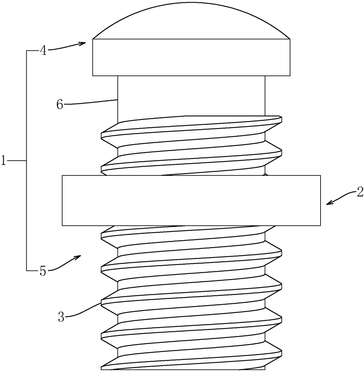
[0045] like figure 2 As shown, an adjusting screw assembly includes a screw member 1 and a nut 2 that are threaded.

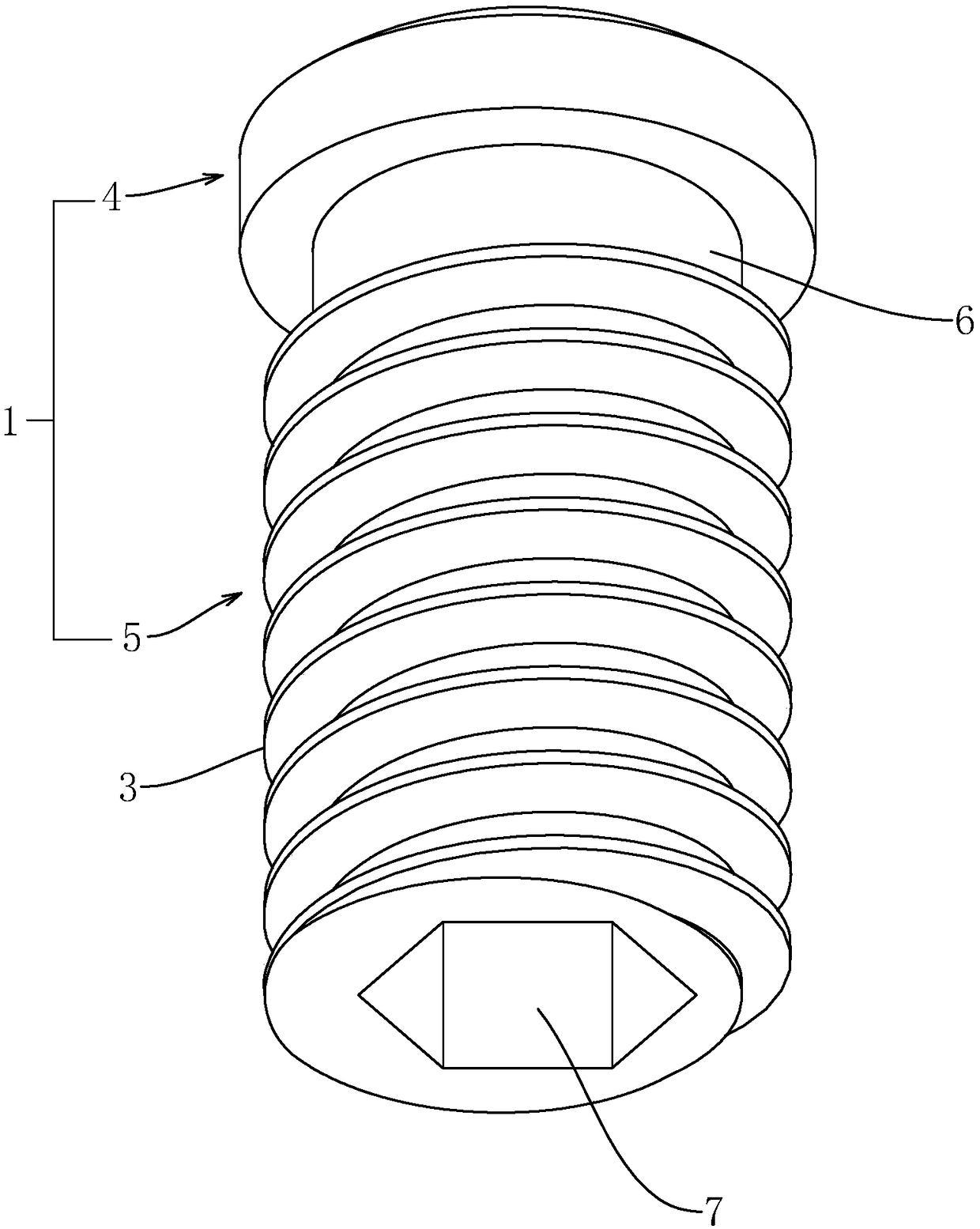
[0046] like figure 2 and image 3 As shown, the screw 1 includes a rod 5 and an arc-shaped end 4 connected to one end of the rod 5. The outer surface of the rod 5 is formed with an external thread 3, and the major diameter of the external thread 3 is A±a. The maximum diameter of the arc surface end 4 perpendicular to the shaft center line of the rod portion 5 is B, B=A+a+b, which is larger than the maximum diameter of the external thread 3 . A connection section 6 with a diameter C is formed at the joint between the rod portion 5 and the arc-shaped end 4, and C is equal to the minor diameter of the external thread 3 . The end of the rod part 5 facing away from the arc surface end 4 is formed with an inner hexagonal groove 7, and the inner hexagonal groove 7 is used as a force receiving part to drive it to rotate.

[0047] like figure 2 and image 3 As ...

Embodiment 2

[0049] A manufacturing process for an adjusting screw assembly, comprising:

[0050] Step a: cold heading

[0051] like Figure 4 As shown, the blank 12 is cold-forged by a cold heading machine. The blank 12 includes a rod 5 and an arc-shaped end 4. The diameter of the arc-shaped end 4 is B, and the diameter of the rod 5 is A±a. An inner hexagonal groove 7 is formed on the end of the rod portion 5 facing away from the arc surface end 4 .

[0052] Step b: Cleaning

[0053] Use a washing machine to remove surface oil stains.

[0054] Step c: Rub teeth

[0055] like image 3 and Figure 5 As shown, the surface of the blank 12 is rubbed by the thread rubbing machine 8 to form the screw 1 . The tooth rubbing machine 8 includes a conveying device 9, a screening device 10 and a tooth rubbing device 11. The conveying device 9 conveys the blanks 12, and the screening device 10 screens the blanks 12 with a fixed orientation to ensure that the processing effect of each blank 12 is t...


PUM


Abstract

The invention discloses an adjusting screw assembly. The adjusting screw assembly has the advantages that a screw part and a nut are not easy to separate. The adjusting screw assembly comprises the screw part and the nut which are in threaded connection; and the screw part comprises a rod part and an arc surface end head connected to one end of the rod part, the outer surface of the rod part is provided with external threads, and the maximum diameter, perpendicular to the shaft axis of the rod part, of the arc surface end head is larger than the large diameter size of the external threads. Themaximum diameter, perpendicular to the shaft axis of the rod part, of the arc surface end head is arranged to be larger than the large diameter size of the external threads so that the position of the nut can be limited by the arc surface end head when the nut rotates to the end, provided with the arc surface end head, of the screw part, then the nut cannot be separated from the screw part from the end provided with the arc surface end head, therefore, when the screw part and the nut are assembled, only by installing the nut at the position, attaching to the arc surface end head, on the screwpart, the nut cannot be easily separated from the screw part.

Description

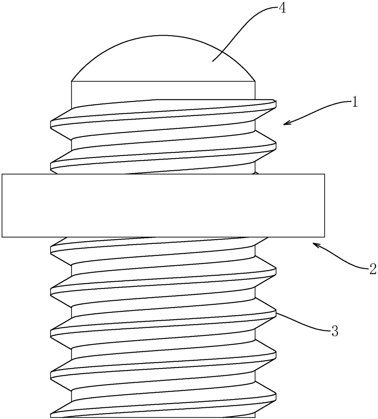
technical field [0001] The present invention relates to an adjusting assembly, more specifically, it relates to an adjusting screw assembly and its manufacturing process. Background technique [0002] like figure 1 As shown, an existing adjusting screw assembly includes a threaded screw 1 and a nut 2, the screw 1 is a cylinder, and the outer surface is processed with external threads 3, and one end of the screw 1 is processed with an arc When the adjusting bolt assembly abuts against the adjustment position, the friction force between the screw member 1 and the abutting surface is relatively small, and at the same time, the abutting surface will not be damaged. [0003] However, this solution has the following problems: for the convenience of installation, screws and nuts are usually combined for sale, and the relative free rotation between the screws and nuts is easy to cause the screws and nuts to be separated. It is not easy to make the screws and nuts Separation requir...

Claims


Application Information

Patent Timeline
IPC IPC(8): F16B35/06F16B35/04F16B23/00F16B41/00B21H3/02B21H9/02
CPCB21H3/02B21H9/02F16B23/0038F16B35/048F16B35/06F16B41/002
Inventor 闻金普
Owner 浙江吉达金属有限公司
Learn More