Traction device and traction method for hoisting pipeline in vertical shaft

A traction device and pipeline technology, applied in the directions of pipeline laying and maintenance, hoisting device, transportation and packaging, etc., can solve the problems of increased material cost, waste of space in the well, and high construction difficulty, so as to reduce the construction difficulty, reduce the workload, The effect of low construction difficulty

Active Publication Date: 2018-09-07
XIAN XD SWITCHGEAR ELECTIC CO LTD +2
View PDF6 Cites 8 Cited by
  • Summary
  • Abstract
  • Description
  • Claims
  • Application Information

AI Technical Summary

Problems solved by technology

[0004] However, this method needs to install vertical rigid guide rails in the shaft, which requires a large amount of work and high construction difficulty
[0005] In addition, the installation of rigid guide rails requires more materials and increases the cost
Furthermore, in order to take into account the future maintenance of the pipeline equipment, the rigid guide rail needs to be permanently reserved, so the down passage where the rigid guide rail is located cannot be reused, resulting in a waste of space in the well; at the same time, the top bridge crane needs to lift the pipeline from the rigid guide rail to each part of the well. Due to the installation location, each platform in the well cannot be directly bui

Method used


Image

  • Traction device and traction method for hoisting pipeline in vertical shaft
  • Traction device and traction method for hoisting pipeline in vertical shaft
  • Traction device and traction method for hoisting pipeline in vertical shaft

Examples


Embodiment Construction

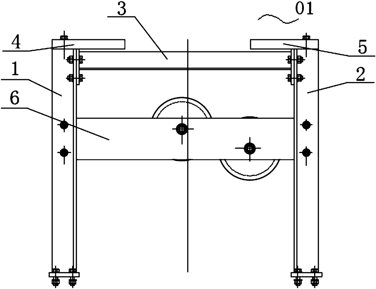
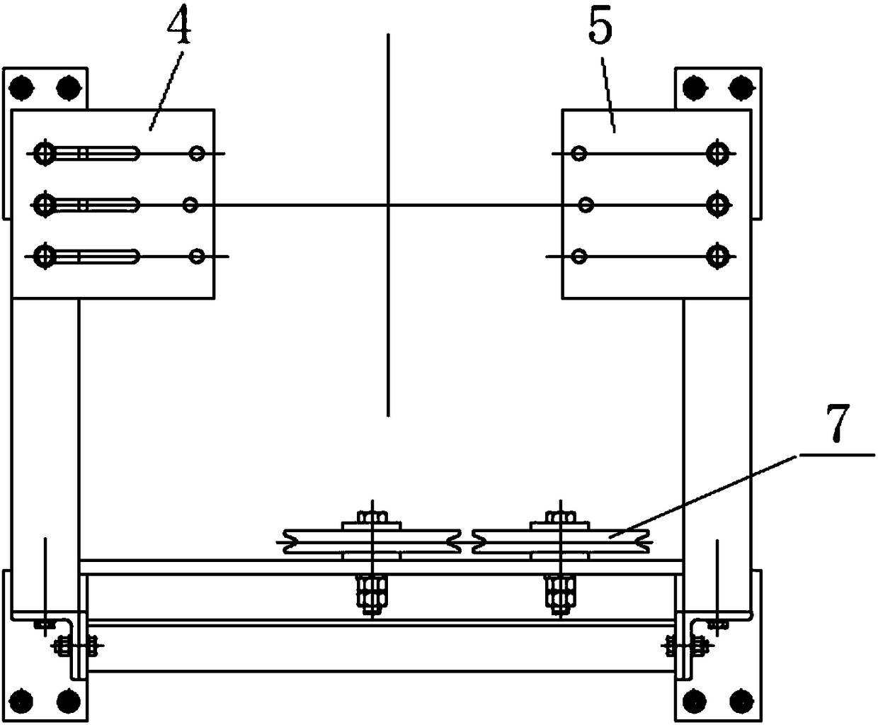
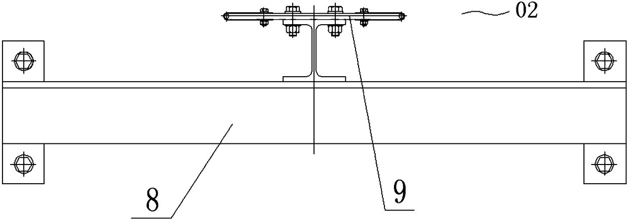
[0065] The embodiment of the invention discloses a traction device for hoisting pipes in a shaft, which uses steel cables to guide the hoisted pipes to be transported down the shaft, avoiding the installation of vertical rigid guide rails on the inner wall of the shaft, less work, and less difficult construction. The embodiment of the present invention also discloses a traction method for hoisting pipelines in a shaft, which is applied to the above traction device, and has the effects of less work and low construction difficulty.

[0066] The following will clearly and completely describe the technical solutions in the embodiments of the present invention with reference to the accompanying drawings in the embodiments of the present invention. Obviously, the described embodiments are only some, not all, embodiments of the present invention. Based on the embodiments of the present invention, all other embodiments obtained by persons of ordinary skill in the art without making cre...


PUM


Abstract

The invention discloses a traction device for hoisting a pipeline in a vertical shaft. The traction device comprises a docking support, a winch, steel cable limiting parts, a limiting sliding block and a crane. The docking support is used for being fixed to a top foot platform. The docking support is provided with fixed pulleys. A steel cable of the winch is wound around the fixed pulleys, and thefree end of the steel cable extends to the bottom of the vertical shaft and is provided with a tension weight in a suspending mode. The steel cable limiting parts are used for being fixed to the inner wall of the vertical shaft or a platform in the vertical shaft and are further used for being connected with the steel cable to prevent the steel cable from swinging in the horizontal direction. Thelimiting sliding block is used for being fixed to the pipeline to be hoisted, is detachably clamped onto the steel cable and can slide along the stable cable. The crane is used for hoisting the pipeline and conveying the pipeline downwards to a mounting position in the vertical shaft along the steel cable. The traction device prevents the steel cable from swinging in the horizontal direction through the steel cable limiting parts, so that the steel cable serves as a guide rail to guide the pipeline to be conveyed to the lower portion of the vertical shaft. The workload can be reduced, and theconstruction difficulty can be reduced. The invention further provides a traction method applied to the traction device.

Description

technical field [0001] The invention relates to the technical field of machinery industry, more specifically, to a traction device for hoisting pipelines in a shaft, and also to a traction method for hoisting pipelines in a shaft. Background technique [0002] In large-scale hydropower stations and nuclear power projects, it often involves the installation of pipeline equipment in shafts, especially in shafts with high drop. The ~800mm pipeline bus section is hoisted vertically into the vertical shaft in turn, docked end to end, fixed by the shaft wall, connected out of the shaft from the bottom of the shaft, and realizes the electrical connection between the downhole equipment and the topside equipment. [0003] In the prior art, when hoisting the pipeline, a rigid guide rail, such as H-shaped steel guide rail, should be installed from top to bottom at a specific position on the shaft wall, and a pre-installed bracket should be established on the top platform of the shaft t...

Claims


Application Information

Patent Timeline
IPC IPC(8): F16L1/036F16L1/09B66C25/00B66D1/28
CPCB66C25/00B66D1/28F16L1/036F16L1/09
Inventor 张涛
Owner XIAN XD SWITCHGEAR ELECTIC CO LTD
Why Eureka
Try Eureka