Device for rapidly calibrating high-precision temperature sensor and calibration and verification method

A temperature sensor and verification method technology, which is applied in the field of rapid calibration of high-precision temperature sensor devices, can solve the problems of time-consuming, labor-intensive, high cost, high input cost, huge work and cost, etc., to improve calibration efficiency and controllability Strong, good heat insulation effect

Pending Publication Date: 2018-09-07
上海雁文智能科技有限公司
View PDF0 Cites 3 Cited by
  • Summary
  • Abstract
  • Description
  • Claims
  • Application Information

AI Technical Summary

Problems solved by technology

In the conventional way, the construction of the laboratory, the layout of electric wires, and network cables require huge work and cost, and because the laboratory itself has a large space, it may even take at least 2 hours to wait for the stability of the laboratory, and the input cost is high and the efficiency is extremely high. Low; in the conventional calibration method, data acquisition is time-consuming, labor-intensive and costly. At the same time, the analog circuit itself is easily disturbed, and multiple data conversions bring unnecessary costs and construction work to data acquisition.

Method used


Image

  • Device for rapidly calibrating high-precision temperature sensor and calibration and verification method
  • Device for rapidly calibrating high-precision temperature sensor and calibration and verification method
  • Device for rapidly calibrating high-precision temperature sensor and calibration and verification method

Examples


Embodiment Construction

[0029] The present invention will be further described in conjunction with the accompanying drawings and specific embodiments. It should be understood that these examples are only used to illustrate the present invention and are not intended to limit the scope of the present invention. In addition, it should be understood that after reading the content taught by the present invention, those skilled in the art may make various changes or modifications to the present invention, and these equivalent forms also fall within the scope defined in the present application.

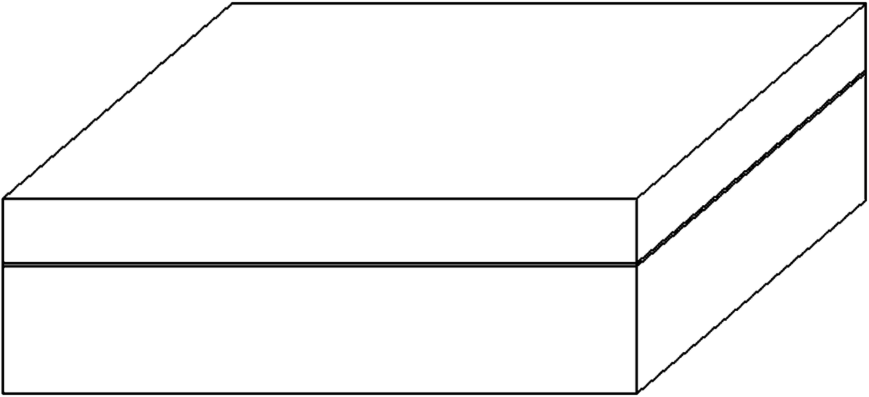
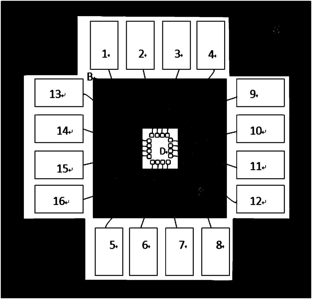
[0030] Such as figure 1 , 2 As shown, the temperature control box of the present invention is about 0.5m 3 The rectangular cubic box mainly includes the upper cover and the lower box. The upper part of the box is completely filled with the box shell and the inside is filled with thermal insulation materials, which are not shown here. The insulation material is PU insulation material, and the thickness of the ins...


PUM

PropertyMeasurementUnit
thicknessaaaaaaaaaa
thicknessaaaaaaaaaa

Abstract

The invention provides a device for rapidly calibrating a high-precision temperature sensor and a calibration and verification method. The device comprises a box body and an upper cover, wherein the interior of the box body is sequentially divided into four regions A, B, C and D from the edge of the box body to the center, the region B is arranged at the center of the interior of the region A, theregion C is arranged at the center of the interior of the region B, the region D is arranged at the center of the interior of the region C, the region B and the region D are slotted, a plurality of porous channels which horizontally traverse the region C are arranged in the region C, the porous channels are communicated with the region B with the region D, a sensor temperature measurement moduleis placed in the region B, a sensor probe is placed in the region D, the porous channels in the region C are used for enabling a wire connecting the temperature measurement module with the probe to pass through, and insulating layers are arranged on the upper cover and in the four regions A, B, C and D respectively. Compared with the traditional calibration way, cost can be reduced, and calibration efficiency and sensor accuracy can be improved.

Description

technical field [0001] The invention mainly relates to the technical field of high-precision temperature sensors, and specifically relates to a device for quickly calibrating high-precision temperature sensors and a method for calibrating and verifying them. Background technique [0002] The high-precision temperature sensor needs to be calibrated before leaving the factory to ensure the measurement accuracy of the sensor. In the conventional calibration method, a large-scale room-type precision laboratory is mainly used, and wires and network cables are laid out on-site in the laboratory, and each sensor (data measuring point) is connected with a computer to obtain data and perform sensor calibration. calibration. In the conventional way, the construction of the laboratory, the layout of electric wires, and network cables require huge work and cost, and because the laboratory itself has a large space, it may even take at least 2 hours to wait for the stability of the labor...

Claims


Application Information

Patent Timeline
Patent Type & Authority Applications(China)
IPC IPC(8): G01K15/00
CPCG01K15/005G01K15/002
Inventor 顾道金
Owner 上海雁文智能科技有限公司
Why Eureka
Try Eureka