
A mechanical micro-sample rapid sampling mechanism

A fast and mechanical technology, applied in the direction of sampling device, etc., can solve the problems of difficult sample acquisition, no non-destructive or micro-destructive rapid sampling device, etc., and achieve the effect of ensuring centering, compact structure and reliable performance

Inactive Publication Date: 2021-09-17
EAST CHINA UNIV OF SCI & TECH
View PDF0 Cites 0 Cited by
  • Summary
  • Abstract
  • Description
  • Claims
  • Application Information

AI Technical Summary

Problems solved by technology

[0003] However, there is no special non-destructive or micro-destructive rapid sampling device at present, which makes it difficult to obtain the samples required for the small punch test or hydraulic bulge test

Method used


Image

  • A mechanical micro-sample rapid sampling mechanism

Examples


Embodiment 1

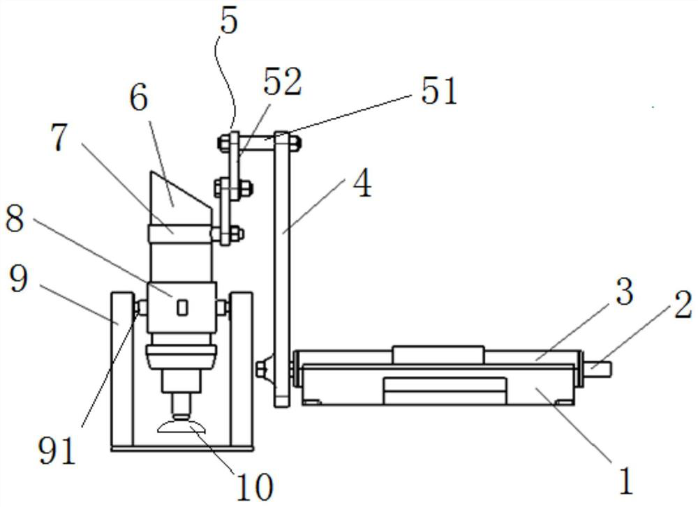
[0023] A mechanical micro-sample rapid sampling mechanism, its structure is as follows figure 1 shown, including:

[0024] Base 9: the top is provided with a horizontal rotating shaft 91;

[0025] Cutter unit 5: comprising a rotary motor 6 and a sampling tool 10 connected to the rotary motor 6, the middle part of the rotary motor 6 is fixed with a hoop frame 8, and is rotatably connected to the horizontal rotating shaft 91 through the hoop frame 8;

[0026] Swing unit: including a box body composed of a base 1 and an upper cover 3, a main shaft 2 fixedly arranged inside the box body, a drive motor (not shown in the figure) arranged at one end of the main shaft 2, and a bottom end fixedly arranged on the main shaft 2 The swing rod 4 at the other end and the ferrule 7 connected to the top of the swing rod 4 through the connection unit 5, the ferrule 7 is sleeved on the upper end of the rotating motor 6.

[0027] Wherein, the connecting unit 5 includes a connecting rod 51 verti...


PUM


Abstract

The invention relates to a mechanical micro-sample rapid sampling mechanism, comprising: a base: a horizontal shaft is arranged on the top; a tool unit: includes a rotary motor and a sampling tool connected with the rotary motor, and the rotary motor is rotatably connected with the horizontal shaft; a swing unit : connected with the upper end of the rotating motor, used to drive the rotating motor to swing around the horizontal shaft. Compared with the prior art, the present invention can realize high-efficiency digging of button-type or spherical-cap-type materials.

Description

technical field [0001] The invention relates to the technical field of pressure vessel inspection, in particular to a mechanical micro-sample rapid sampling mechanism. Background technique [0002] In my country's petrochemical, electric power and other industries, there are many pressure pipelines and other equipment that serve in harsh environments. These equipment have been operating under high temperature, high pressure, hydrogen corrosion and other conditions for a long time, and the service environment is very harsh. In order to ensure safety within the service period, these pressure equipment are often designed with a higher safety factor and a larger safety margin to improve safety. Considering the requirements of economy and safety, people hope to know the mechanical properties of the equipment in a timely and accurate manner without affecting the service of the equipment, so as to evaluate the performance degradation in time. The small punch test or the hydraulic ...

Claims


Application Information

Patent Timeline
Patent Type & Authority Patents(China)
IPC IPC(8): G01N1/08
CPCG01N1/08
Inventor 陈汝康罗安王建文王琼琦涂善东张安逸董姣姣程敏杰
Owner EAST CHINA UNIV OF SCI & TECH
Learn More