
Optical fingerprint collection method and device and user terminal

A fingerprint collection and optical technology, applied in character and pattern recognition, instruments, electrical digital data processing, etc., can solve problems such as poor visual effect, reduced waterproof performance, visual fatigue, etc.

Active Publication Date: 2018-09-07
ONEPLUS TECH SHENZHEN
View PDF7 Cites 2 Cited by
  • Summary
  • Abstract
  • Description
  • Claims
  • Application Information

AI Technical Summary

Problems solved by technology

[0003] At present, the mainstream fingerprint recognition technologies used in the market mainly include the following three types: capacitive pressing technology, optical fingerprint recognition technology and ultrasonic fingerprint recognition technology; among them, capacitive pressing technology is relatively mature, but if the fingerprint has other interference, the accuracy rate will be greatly reduced; Ultrasonic fingerprint recognition technology needs to open holes on the device, which reduces the waterproof performance of the device; while optical fingerprint recognition technology is more and more favored by more and more intelligent terminal R&D and production enterprises due to its fast response speed and accurate recognition rate
[0004] When the existing smart terminals using optical recognition perform fingerprint recognition, all areas of the smart terminal or the fingerprint collection area as a whole need to be set to a high-light mode, and the fingerprint features are collected and extracted through the high-light mode. The whole process of the collection is kept in a high-gloss state, so that when the user is collecting fingerprints, especially at night, high-light glare will cause glare, visual fatigue, and even cause instant blindness to a certain extent. The visual effect is not good and the user experience is poor.

Method used

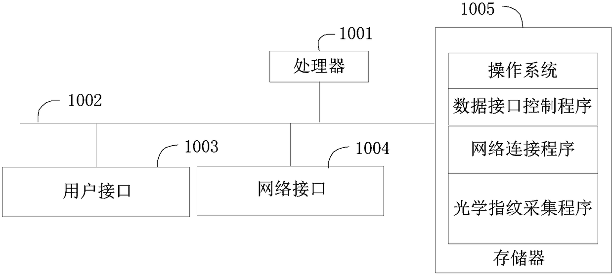

Image

  • Optical fingerprint collection method and device and user terminal
  • Optical fingerprint collection method and device and user terminal
  • Optical fingerprint collection method and device and user terminal

Examples


Embodiment 1

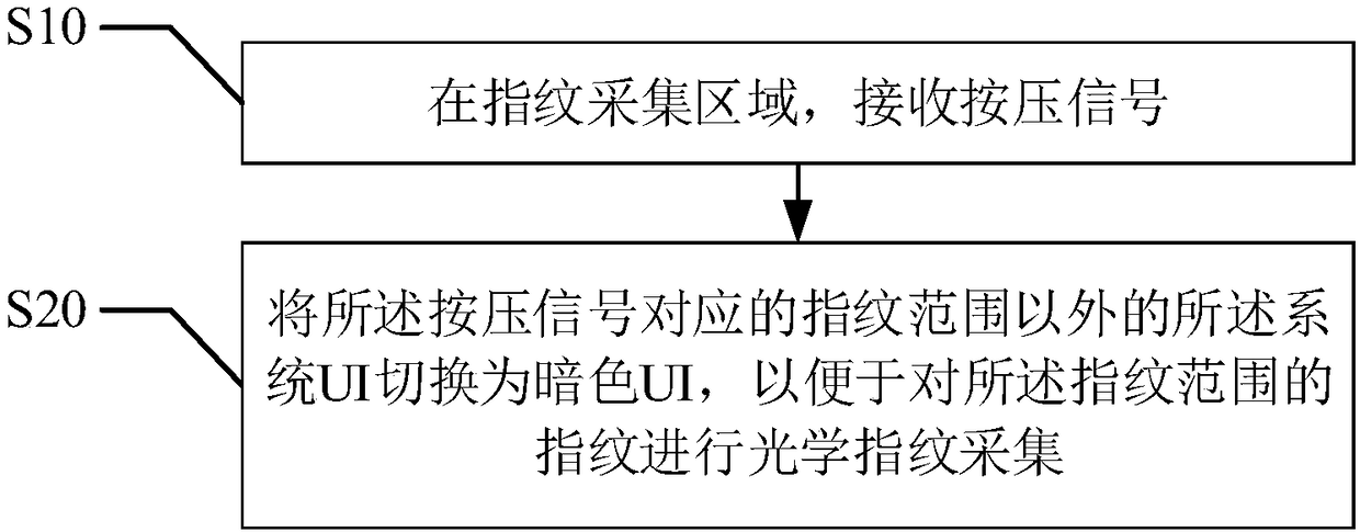
[0059] refer to figure 2 , the first embodiment of the present invention provides an optical fingerprint collection method, including:

[0060] Step S10, receiving a pressing signal in the fingerprint collection area;

[0061] The optical fingerprint collection method described in the present invention can be applied to fingerprint collection equipment using optical fingerprint recognition technology, for example, it can include but not limited to the interactive interface of mobile phones, tablet computers, attendance machines, gate authentication devices, etc., in this In the embodiment, it can be applied to a smart phone or a tablet computer with a touch screen and using optical fingerprint identification technology.

[0062] As mentioned above, the fingerprint collection area is the specified area that appears on the interactive interface, such as the screen, under the command of fingerprint collection. For example, when performing fingerprint authentication, it can be t...

Embodiment 2

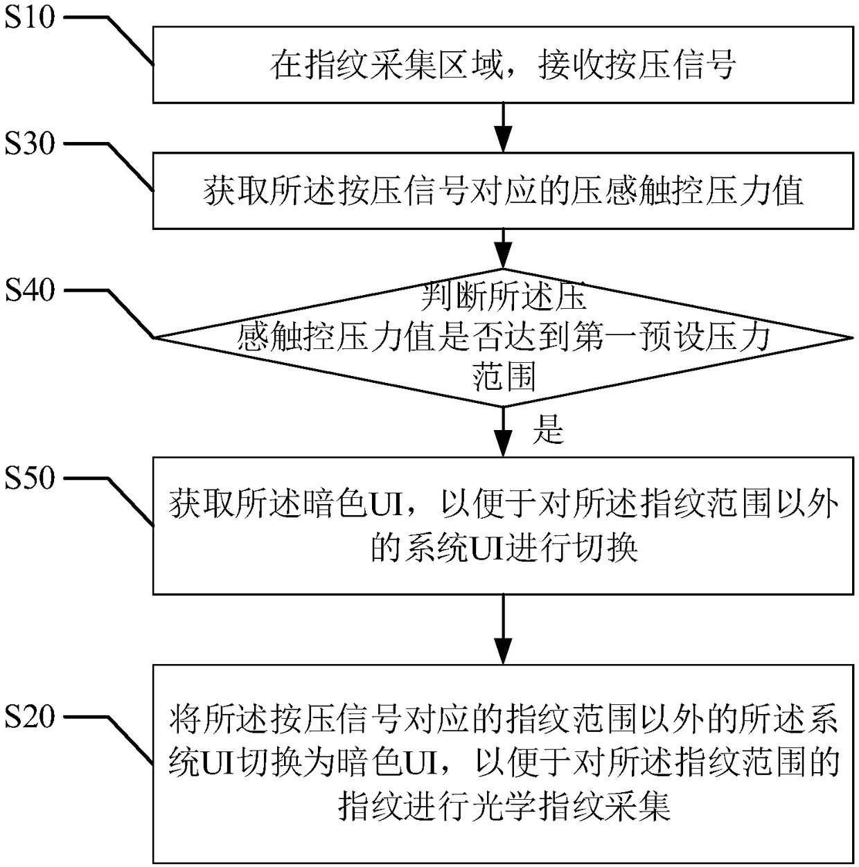
[0071] refer to image 3 , the second embodiment of the present invention provides an optical fingerprint collection method, based on the above figure 2 In the first embodiment shown, before the step S20 of "switching the system UI outside the fingerprint range corresponding to the pressing signal to a dark UI, so as to perform optical fingerprint collection on the fingerprints in the fingerprint range", there is also include:

[0072] Step S30, acquiring the pressure-sensitive touch pressure value corresponding to the pressing signal;

[0073] It should be understood that the pressure-sensitive touch technology may include but not limited to ClearForce pressure-sensitive touch solution, Force Touch technology, 3D Touch touch technology and other technologies.

[0074] As mentioned above, it needs to be understood that pressure-sensitive touch (pressure touch technology) is equipped with force sensors at the four corners of the screen, which can sense the pressure of pressi...

Embodiment 3

[0081] refer to Figure 4 , the third embodiment of the present invention provides an optical fingerprint collection method, based on the above image 3 In the second embodiment shown, after the step S20 of "switching the system UI outside the fingerprint range corresponding to the pressing signal to a dark UI, so as to perform optical fingerprint collection on the fingerprints in the fingerprint range", further include:

[0082] Step S60, judging whether the pressure-sensitive touch pressure value reaches a second preset pressure range;

[0083] As mentioned above, the second preset pressure range is the preset condition for starting fingerprint feature acquisition and fingerprint recognition, that is, when the pressure-sensitive touch pressure value reaches the second preset pressure range, the user’s fingerprint range starts to be detected. Fingerprints are collected.

[0084] In this embodiment, the pressure value in the second preset pressure range is greater than the ...


PUM


Abstract

The invention provides an optical fingerprint collection method and device and a user terminal. The method includes: receiving a pressing signal in a fingerprint collection area; and switching systemUI (User Interface) outside a fingerprint range, which corresponds to the pressing signal, to dark-color UI to facilitate optical fingerprint collection on a fingerprint of the fingerprint range. According to the method provided by the invention, system UI of the fingerprint range is switched to high-light fingerprint collection UI in optical fingerprint collection, that is, the range of fingerprint pressing is set to a high-light state so as to realize collection of the optical fingerprint, the other areas still maintain the original UI and original light ray intensity, problems of glare andvisual fatigue due to that all the areas are in a high-light mode in fingerprint collection are avoided, a visual effect is good, and better user experience is provided.

Description

technical field [0001] The present invention relates to the technical field of fingerprint collection, and more specifically, to an optical fingerprint collection method, device and user terminal. Background technique [0002] Fingerprint identification refers to identification by comparing the detailed feature points of different fingerprints. Fingerprint recognition technology involves image processing, pattern recognition, computer vision, mathematical morphology, wavelet analysis and many other disciplines. Because everyone's fingerprints are different, even between the ten fingers of the same person, there are obvious differences in fingerprints, so fingerprints can be used for identification. [0003] At present, the mainstream fingerprint recognition technologies used in the market mainly include the following three types: capacitive pressing technology, optical fingerprint recognition technology and ultrasonic fingerprint recognition technology; among them, capaciti...

Claims


Application Information

Patent Timeline
IPC IPC(8): G06K9/00G06F3/0481
CPCG06F3/0481G06V40/1324
Inventor 刘衍陶凯
Owner ONEPLUS TECH SHENZHEN
Learn More