A transmitter of a multi-channel coherent optical communication device and the multi-channel coherent optical communication device

A technology of coherent optical communication and transmitting end, applied in the information field, can solve difficult problems such as multi-channel small size and low power consumption, increase operator costs, increase overall power consumption of modules, etc.

Active Publication Date: 2020-04-21
HUAWEI TECH CO LTD
View PDF5 Cites 0 Cited by
  • Summary
  • Abstract
  • Description
  • Claims
  • Application Information

AI Technical Summary

Problems solved by technology

[0004] However, in the above solution, in order to meet the Tbit rate requirements of a single line card in the future, multiple modules can be placed on a single line card. If the data rate of each module is 100G bits, only 10 modules can meet the Tbit rate of a single board. need
Since each coherent optical module (DCO, Digital coherent optics) needs to use a DSP chip, the overall power consumption of the module is increased compared with the non-coherent client-side module. Therefore, when the number of modules increases, the heat dissipation capacity of the single board is difficult to meet need
At the same time, the power consumption cost of the computer room is also an important part of the operator's operating cost, so it will further increase the operator's cost
At the same time, most of the existing coherent modules use single-channel optical devices and electrical devices, and the device itself and the DSP chip are not packaged together, so it is difficult to achieve multi-channel small size and low power consumption

Method used


Image

  • A transmitter of a multi-channel coherent optical communication device and the multi-channel coherent optical communication device
  • A transmitter of a multi-channel coherent optical communication device and the multi-channel coherent optical communication device
  • A transmitter of a multi-channel coherent optical communication device and the multi-channel coherent optical communication device

Examples


Embodiment 1

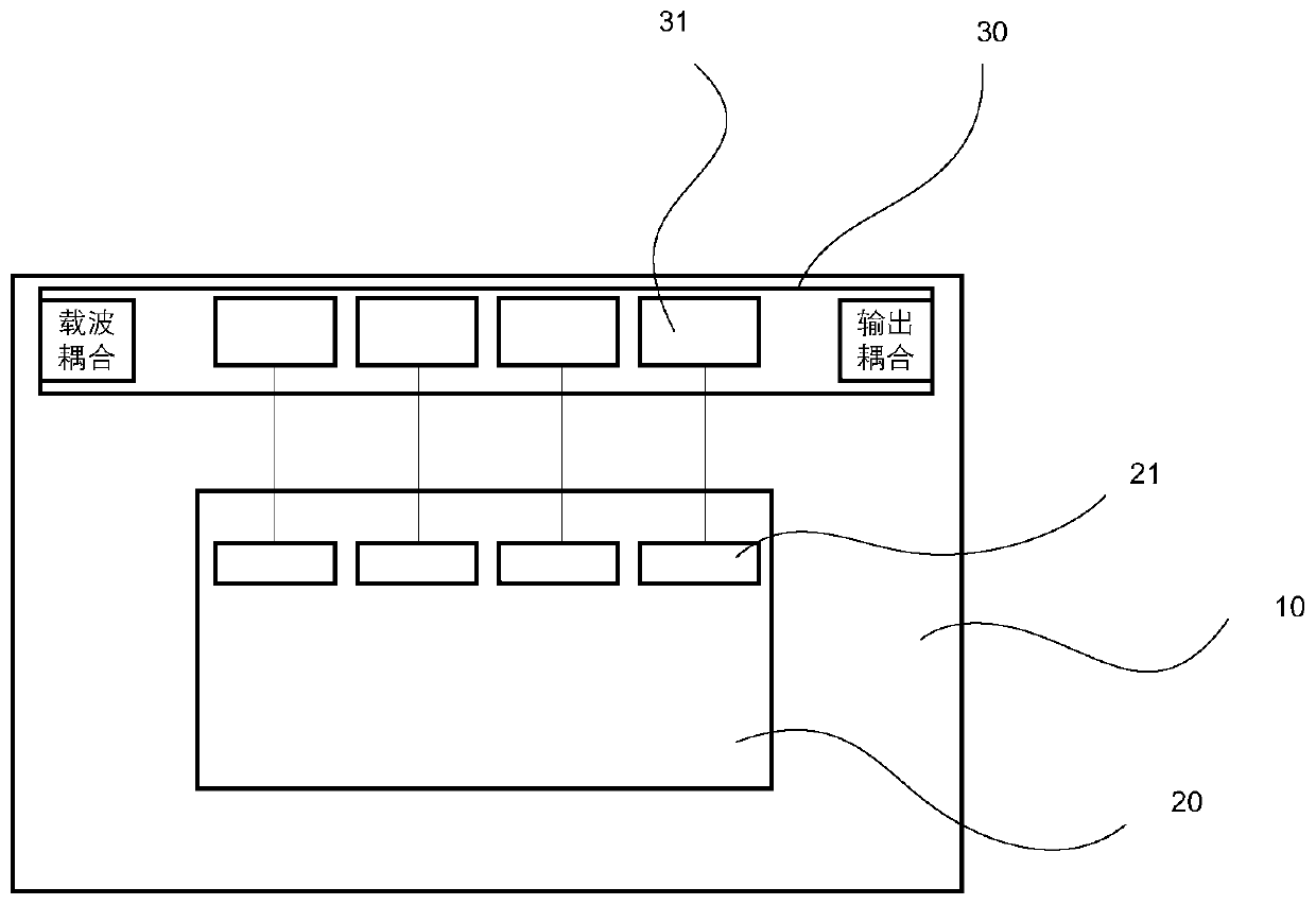
[0034] like figure 1 and figure 2 As shown, in this embodiment, for the convenience of description, the multi-channel optical digital signal processor adopts a four-channel optical digital signal processor 20 , and the four-channel optical digital signal processor 20 includes four digital-to-analog converters 21 . The corresponding multiplexer module 30 includes four modulators 31 .

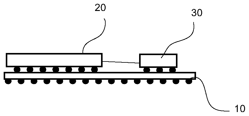
[0035] In specific settings, such as figure 1 As shown, the four-channel optical digital signal processor 20 provided in this embodiment is disposed on the substrate 10 by ball bonding, and the four digital-to-analog converters 21 are disposed on the same side of the four-channel optical digital signal processor 20, namely four The four output ports of the channel optical digital signal processor 20 are located on the same side of the four channel optical digital signal processor 20 . The multiplexer module 30 composed of four modulators 31 is disposed on the substrate 10 and located at one s...

Embodiment 2

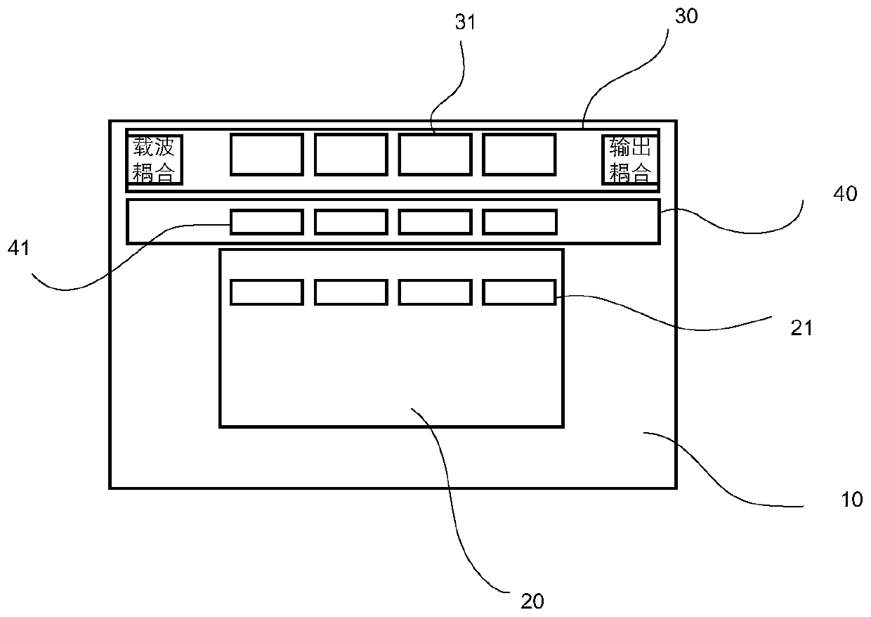
[0038] like image 3 and Figure 4 As shown, in this embodiment, for the convenience of description, the multi-channel optical digital signal processor adopts a four-channel optical digital signal processor 20 , and the four-channel optical digital signal processor 20 includes four digital-to-analog converters 21 . The corresponding multiplexer module 30 includes four modulators 31 . In this embodiment, the transmitter and the figure 1 Compared with the first embodiment shown, in addition to the structure and arrangement in the first embodiment, the transmitting end further includes a multi-channel radio frequency driver module 40 .

[0039] In specific settings, the multi-channel radio frequency driver module 40 is disposed on the substrate 10 and is located between the four-channel optical digital signal processor 20 and the multiplexer module 30. In specific settings, the multi-channel radio frequency driver module 40 It includes a radio frequency driver 41 (Driver) corr...

Embodiment 3

[0045] like Image 6 and Figure 7 As shown, in this embodiment, for the convenience of description, the multi-channel optical digital signal processor adopts a four-channel optical digital signal processor 20 , and the four-channel optical digital signal processor 20 includes four digital-to-analog converters 21 . The corresponding multiplexer module 30 includes four modulators 31 . In this embodiment, the transmitter and the image 3 and Image 6 Compared with the second embodiment shown, in addition to the structure and arrangement in the second embodiment, the transmitting end further includes a multi-channel optical amplifier module 50 . or as figure 1 The structure of the transmitting end in the shown embodiment 1 is added with a multi-channel optical amplifier module 50 .

[0046] In specific settings, the multi-channel optical amplifier module 50 includes a plurality of optical amplifiers 51 , and in specific settings, the plurality of optical amplifiers 51 are ar...


PUM


Abstract

The invention provides a transmitting terminal of a multi-channel coherent light communication device and a multi-channel coherent light communication device. The transmitting terminal comprises a substrate, a multi-channel light digital signal processor, and a multi-channel modulator module, wherein the multi-channel light digital signal processor is arranged on the substrate, and the multi-channel modulator module is arranged on the substrate; the transmitting terminal further comprises a packaging layer which packages the multi-channel light digital signal processor and the multi-channel modulator module on the substrate, wherein the multi-channel modulator module comprises a modulator which is connected with each channel of the multi-channel light digital signal processor in a one-to-one correspondence mode. According to the technical scheme, the transmitting terminal in the multi-channel coherent light communication device is used as a whole device; compared with the prior art ofadopting one transmitting terminal and one transmitting terminal to form a device, the size of the module can be greatly reduced under the condition of obtaining the same bit rate, so that the transmission capacity of the single board is improved; moreover, the transmitting terminal is independently packaged, the optical crosstalk and the radio frequency crosstalk between the transmitting terminals are reduced compared with the mixed packaging with transmitting and receiving together.

Description

technical field [0001] The present application relates to the field of information technology, and in particular, to a transmitter of a multi-channel coherent optical communication device and a multi-channel coherent optical communication device. Background technique [0002] With the increase of network system traffic, the communication system needs to increase the transmission capacity of the system under the condition that the rack volume remains unchanged, thereby realizing high-density transmission. By reducing the size of the module, such as the use of CFP (C form-factor pluggable, 100G-shaped pluggable), CFP2 and CFP4 into optical modules, the data rate per unit volume can be improved. For line-side optical modules, modules using coherent technology can support longer transmission distances due to the use of DSP (digital signal processing, optical digital signal processing) algorithm chips to compensate for dispersion, etc. Typically 100Gbits per second. [0003] Th...

Claims


Application Information

Patent Timeline
Patent Type & Authority Patents(China)
IPC IPC(8): H04B10/50H04B10/516
CPCH04B10/50H04B10/501H04B10/516
Inventor 曹攀曾嘉宏汪永忠熊伟吴双元
Owner HUAWEI TECH CO LTD
Why Eureka
Try Eureka