Cutting equipment for manufacturing iron picture and iron picture cutting method using equipment

A kind of equipment, iron painting technology, applied in shearing machine equipment, metal processing equipment, shearing device and other directions, can solve the problems that scissors are difficult to stabilize, laborious and time-consuming, and require high operator skills, so as to achieve stable and convenient use, reduce costs, and save production. effect of time

Pending Publication Date: 2018-09-11
芜湖储铁艺铁画设计有限公司
View PDF21 Cites 0 Cited by
  • Summary
  • Abstract
  • Description
  • Claims
  • Application Information

AI Technical Summary

Problems solved by technology

[0005] The purpose of the present invention is to provide a cutting device for making iron paintings, so as to solve the defects in the prior art that when cutting thin iron plates, it is laborious and time-consuming, the scissors are difficult to stabilize, and the operator requires high skills.

Method used


Image

  • Cutting equipment for manufacturing iron picture and iron picture cutting method using equipment
  • Cutting equipment for manufacturing iron picture and iron picture cutting method using equipment
  • Cutting equipment for manufacturing iron picture and iron picture cutting method using equipment

Examples


Embodiment Construction

[0032] With reference to the accompanying drawings, the specific implementation of the present invention will be further described in detail through the description of the embodiments to help those skilled in the art have a more complete, accurate and in-depth understanding of the inventive concept and technical solution of the present invention.

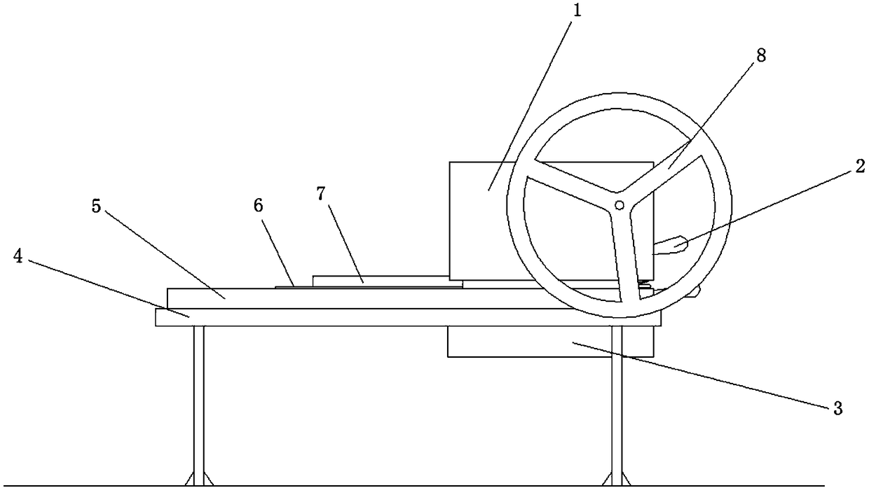
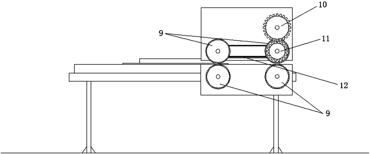
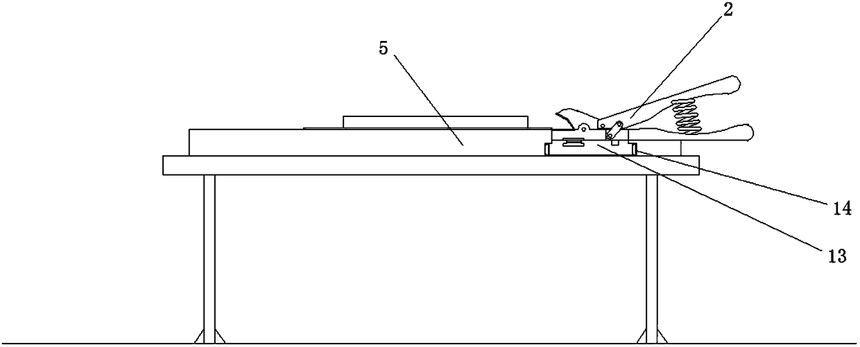
[0033] Such as Figure 1 to Figure 6 As shown, the present invention provides a cutting device for making iron paintings, which includes a workbench 4, an equipment substrate 5 installed on the workbench 4, an iron plate conveying mechanism, and a cutting mechanism. The cutting mechanism includes a scissors sliding seat 13 and an iron plate scissors 2 mounted on the scissors sliding seat 13. Before use, the workbench 4 is adjusted to ensure the level of the top plane of the equipment substrate 5.

[0034] This equipment takes the direction the operator faces when operating as the front, and the operator sits behind the equipment to work...


PUM


Abstract

The invention discloses cutting equipment for manufacturing an iron picture. The cutting equipment comprises a workbench, an equipment base plate, an iron plate conveying mechanism and a cutting mechanism, wherein the equipment base plate is installed on the workbench, a scissors guide rail is arranged on the back part of the equipment base plate in a transverse direction, the iron plate conveyingmechanism comprises conveying boxes which are respectively arranged on both sides of the equipment base plate, the conveying box on one side comprises an upper conveying box and a lower conveying boxwhich are respectively installed on the upper and lower surfaces of the equipment base plate, plate conveying wheels are installed in the upper conveying box and the lower conveying box by virtue ofrotating shafts, the plate conveying wheels of the upper conveying box and the lower conveying box are opposite to each other, the spacing between the wheel surfaces of the plate conveying wheels adapts to the thickness of a to-be-cut iron plate, the plate conveying wheel of the upper conveying box is in driving connection with a rotating wheel handle on the outer side of the upper conveying box by virtue of a transmission mechanism, and the cutting mechanism comprises a scissors sliding seat which is installed in the scissors guide rail in a sliding mode and a pair of iron plate scissors installed on the scissors sliding seat by virtue of a rotating shaft mechanism. The cutting equipment has the advantages of stability and convenience in use, the working efficiency of cutting the iron plate is effectively improved, and the cutting qualified rate is effectively increased.

Description

Technical field [0001] The invention relates to the field of iron paintings, in particular to a cutting device for making iron paintings and an iron painting cutting method using the equipment. Background technique [0002] In the field of iron painting, the larger part of the traditional production method is directly forged, but the forging method is time-consuming and laborious, and the physical skills of the corresponding producer are very high. The invention patent with the announcement number CN101791927B discloses a method for making iron art paintings. After drawing and redrawing, the iron plate is cut, and the rough shape is cut out and then beaten. The method is relatively simple to operate, and the manufacturing efficiency is improved. [0003] However, the thin iron plates used to make iron paintings still require considerable skill and arm strength when cutting. Even if there are patterns on the thin iron plates, the cutting must be done with great care. Therefore, th...

Claims


Application Information

Patent Timeline
Patent Type & Authority Applications(China)
IPC IPC(8): B23D31/00B23Q35/10B44C5/04
CPCB23D31/00B23Q35/10B44C5/0415B44C5/0446
Inventor 储铁艺李庆
Owner 芜湖储铁艺铁画设计有限公司
Why Eureka
Try Eureka