Cap feeding device of encapsulated edible oil container

A technology for edible oil and containers, which is applied in the field of cap feeding devices for packaging edible oil containers, which can solve the problems of cap conveying jamming, inconvenient operation, and uneven space spacing of slideways, etc., and achieves high degree of automation, convenient operation, and simple structure Effect

Inactive Publication Date: 2018-09-11
四川巴蜀乡油脂有限公司
View PDF0 Cites 3 Cited by
  • Summary
  • Abstract
  • Description
  • Claims
  • Application Information

AI Technical Summary

Problems solved by technology

At present, the commonly used cover feeding slideway is mainly composed of several fixed rectangular frames welded with steel bars. In the application process, there are the following deficiencies: 1. Because there is no positioning reference, the steel bars are directly welded on the fixed frame, resulting in the cross-section of the slideway The space spacing is uneven, which leads to the jamming phenomenon of the cover body in the area where the slideway gap is too small, and the phenomenon of overlapping and jamming of multiple plastic covers in the area where the slideway gap is too large, causing the system to stop under the action of the automatic control signal; 2. For the overall slideway composed of long steel bars surrounding the conveying space, it is difficult to control the machining accuracy of the slideway radian in its manufacturing, which often leads to on-site correction of the slideway radian during installation, which easily causes changes in the steel bar gap, which in turn causes subsequent 3. The cover emptying mechanism included (when changing the cover type of different colors, the produced cover should be emptied) is usually placed on the side of the slideway, which cannot completely clear the cover body smoothly, and Inconvenient operation, which affects the efficiency of automatic delivery

Method used


Image

  • Cap feeding device of encapsulated edible oil container

Examples


Embodiment

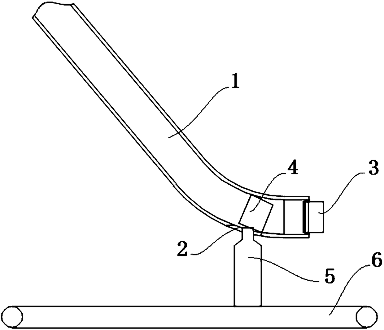
[0017] Such as figure 1 As shown, a cap feeding device for packaging edible oil containers of the present invention includes a bottle cap conveying slide 1, the bottle cap conveying slide 1 is placed in an inclined shape, and the bottle cap 4 is affected by its own gravity on the bottle cap conveying slide 1 Automatically slide down, the bottom of the bottle cap conveying slideway 1 is provided with an edible oil container cover notch 2, and the bottle cap 4 cross section on the edible oil container cover notch 2 forms a set angle with the horizontal plane. The included angle is 45 degrees. The outlet end of the bottle cap conveying slide 1 is provided with an elastic baffle 3. There are two elastic baffles 3. The two elastic baffles 3 are respectively located at the left and right ends of the outlet end of the bottle cap conveying slide 1. Two elastic baffles 3 are hinged to the bottle cap conveying slide 1, and the two elastic baffles 3 are used to close the outlet of the bo...


PUM


Abstract

The invention discloses a cap feeding device of an encapsulated edible oil container. The cap feeding device comprises a bottle cap conveying slide rail which is arranged in an inclined mode, whereina bottle cap automatically slides downwards from a bottle cap conveying slide rail as a result of action of gravity of the bottle cap; a cap taking slot hole of the edible oil container is formed in the bottom of the bottle cap conveying slide rail; a set included angle is formed between the cross section of the bottle cap on a cap taking slot hole of the edible oil container and the horizontal plane; the included angle is an acute angle; an outlet end of the bottle cap conveying slide rail is equipped with two elastic baffle plates; the two elastic baffle plates are separately positioned at left and right ends of the bottle cap conveying slide rail; the two elastic baffle plates are hinged with the bottle cap conveying slide rail; and the two elastic baffle plates are used for closing anoutlet of the bottle cap conveying slide rail. The cap feeding device is novel in design, is convenient in operation, is simple in structure, is low in energy consumption, is high in degree of automation, and is suitable for large-scale production.

Description

technical field [0001] The invention relates to the technical field of edible oil packaging equipment, in particular to a cap feeding device for packaging edible oil containers. Background technique [0002] In the field of filling production, the production process is basically equipped with an automatic capping system, which generally consists of a cap unscrambling machine, a cap feeding slide, and a capping machine. Among them, the cap feeding chute is the cap conveying device connecting the cap unscrambling machine and the capping machine, and the cap feeding chute is also different according to the shape of the cap. At present, the commonly used cover feeding slideway is mainly composed of several fixed rectangular frames welded with steel bars. In the application process, there are the following deficiencies: 1. Because there is no positioning reference, the steel bars are directly welded on the fixed frame, resulting in the cross-section of the slideway The space spa...

Claims


Application Information

Patent Timeline
IPC IPC(8): B65G11/02B67B3/00
CPCB65G11/023B67B3/00
Inventor 王安体王长严
Owner 四川巴蜀乡油脂有限公司
Why Eureka
Try Eureka