Telescopic vehicle blocking rod device based on security technology and protection engineering

A safety technology, the technology of the traffic stop bar, which is applied in the field of telescopic traffic stop bar device, can solve the problems of large inertia and easy damage of the traffic stop bar, and achieve the effect of small inertia, rapid expansion and contraction, compact and reasonable structure

Inactive Publication Date: 2018-09-11
HENAN FUDIAN ELECTRONICS TECH CO LTD
View PDF6 Cites 4 Cited by
  • Summary
  • Abstract
  • Description
  • Claims
  • Application Information

AI Technical Summary

Problems solved by technology

[0005] The purpose of the present invention is: in order to solve the technical problem that the existing traffic stop bar adopts

Method used


Image

  • Telescopic vehicle blocking rod device based on security technology and protection engineering
  • Telescopic vehicle blocking rod device based on security technology and protection engineering
  • Telescopic vehicle blocking rod device based on security technology and protection engineering

Examples


Embodiment 1

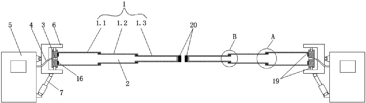
[0027] like Figures 1 to 5 As shown in the figure, this embodiment provides a telescopic parking bar device based on safety technology prevention engineering, including two symmetrically arranged parking bar assemblies 1, and the parking bar assembly 1 includes a first-stage hollow rod 1.1, a second-stage The hollow rod 1.2 and the third-stage hollow rod 1.3, the second-stage hollow rod 1.2 is movably clamped in the first-stage hollow rod 1.1, the third-stage hollow rod 1.3 is movably clamped in the second-stage hollow rod 1.2, the first-stage hollow rod 1.2 The interior of the hollow rod 1.1, the second-stage hollow rod 1.2 and the third-stage hollow rod 1.3 communicate with each other and form a closed cavity 2. The side end of the first-stage hollow rod 1.1 away from the second-stage hollow rod 1.2 is provided with a cavity 2. The connected oil hole 3, the oil hole 3 is connected with the oil pipe 4, the other end of the oil pipe 4 is connected with the hydraulic station 5...

Embodiment 2

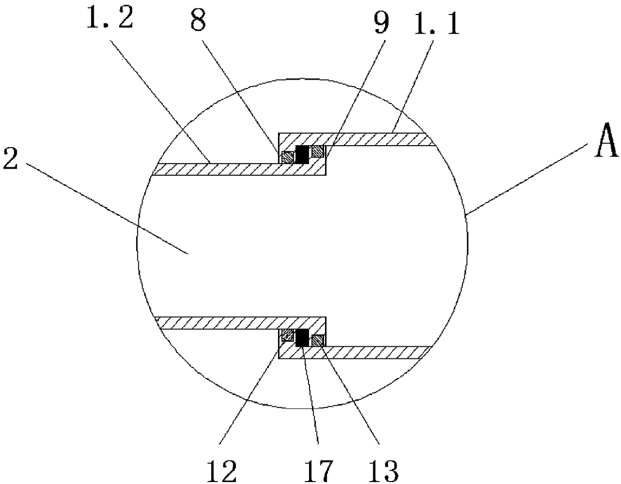
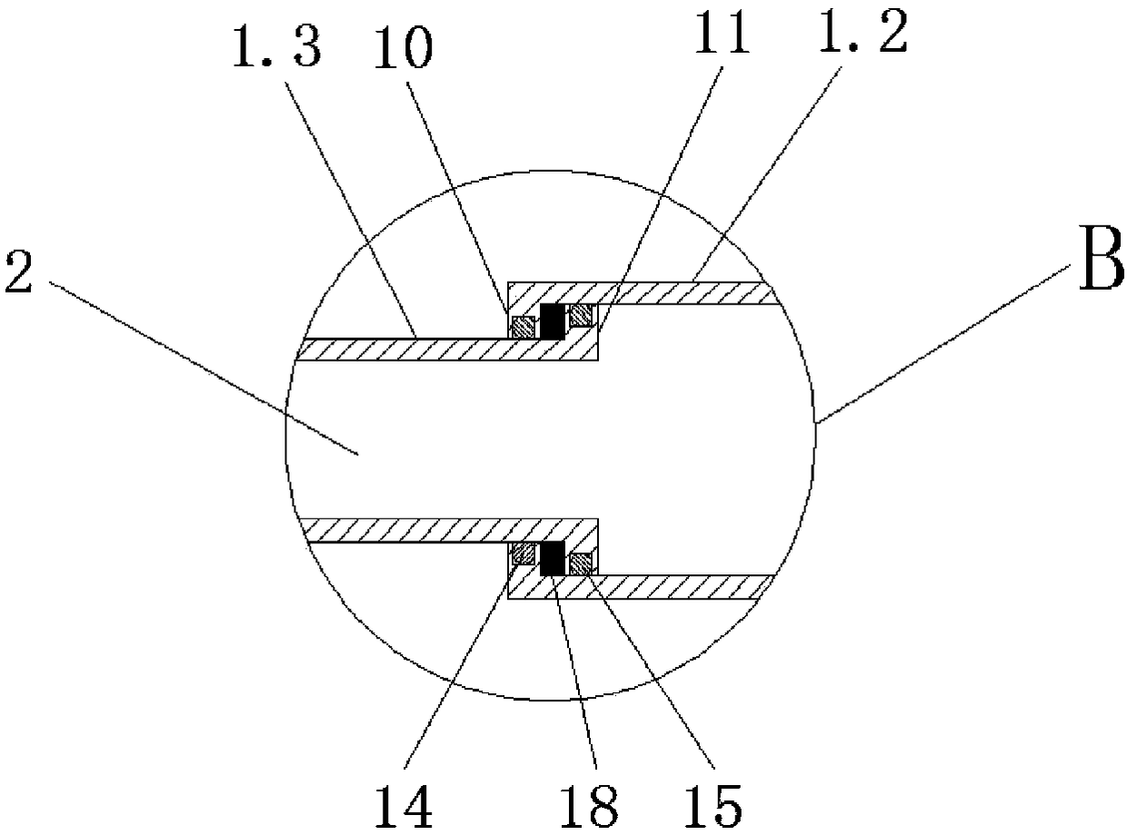
[0030] like Figures 1 to 3 As shown, this embodiment is further optimized on the basis of Embodiment 1. Specifically, the end of the first-stage hollow rod 1.1 away from the seat body 6 is provided with a circle of inwardly turned bosses A8, and the second-stage hollow rod One end of 1.2 is provided with a circle of bosses B9 that are turned outwards and matched with the bosses A8. The bosses B9 are close to the inner wall of the first-stage hollow rod 1.1, and the other end of the second-stage hollow rod 1.2 is provided with a circle of inward-turned protrusions. In the stage C10, one end of the third-stage hollow rod 1.3 is provided with a circle of bosses D11 that are turned outward and cooperate with the boss C10, and the boss D11 is close to the inner wall of the second-stage hollow rod 1.2.

[0031] In this embodiment, when the boss D on the third-stage hollow rod clamps the boss C on the second-stage hollow rod, the third-stage hollow rod and the second-stage hollow ro...

Embodiment 3

[0033] like Figures 1 to 3 As shown, this embodiment is further optimized on the basis of Embodiment 2. Specifically, the boss A8 is provided with a number of universal balls A12 in contact with the outer wall of the second-stage hollow rod 1.2, and the boss B9 is provided with a A number of universal balls B13 in contact with the inner wall of the first-stage hollow rod 1.1, a number of universal balls C14 in contact with the outer wall of the third-stage hollow rod 1.3 inside the boss C10, and a number of universal balls C14 in contact with the second-stage hollow rod inside the boss D11. The universal ball D15 that the inner wall of the rod 1.2 contacts.

[0034] In this embodiment, when the third-stage hollow rod slides in the second-stage hollow rod, the arrangement of the universal ball C and the universal ball D can reduce the friction between the third-stage hollow rod and the second-stage hollow rod In the same way, when the second-stage hollow rod slides in the fir...


PUM


Abstract

The invention discloses a telescopic vehicle blocking rod device based on security technology and protection engineering, relating to the technical field of security technology and protection engineering. The telescopic vehicle blocking rod device comprises two vehicle blocking rod assemblies which are symmetrically distributed, wherein the vehicle blocking rod assemblies comprise first-stage hollow rods, second-stage hollow rods and third-stage hollow rods, the second-stage hollow rods are movably clamped into the first-stage hollow rods, the third-stage hollow rods are movably clamped into second-stage hollow rods, and the insides of the first-stage hollow rods, the second-stage hollow rods and the third-stage hollow rod are communicated to form a closed cavity; oil holes communicated with the cavity are formed in the side ends, far from the second-stage hollow rods, of the first-stage hollow rods, and oil pipes are connected to the oil holes; hydraulic stations are connected to theother ends of the oil pipes, seat bodies are connected to the side ends of the first-stage hollow rods, and the other side ends of the seat bodies are hinged to the side ends of the hydraulic stations; and the hydraulic cylinders are hinged to the bottoms of the seat bodies, and the other ends of the hydraulic cylinders are hinged of the side ends of the hydraulic stations. The telescopic vehicleblocking rod device has the advantages of simple structure, low energy consumption, smoothness in operation and long service life.

Description

technical field [0001] The invention relates to the technical field of safety technology prevention engineering, and more particularly to a telescopic vehicle blocking bar device based on safety technology prevention engineering. Background technique [0002] There will be a parking bar device at the gate of the toll station or the parking lot. The purpose is to manage the access rights of vehicles. Therefore, the parking bar device is an important means of safety technology prevention. The traffic bar is generally manual and automatic. The manual parking bar has a simple structure and is generally used at the gate of the community, but it requires manual operation. Now most of the parking bars have functions such as automatic control, which are more inclined to intelligent development. This automatic parking bar is mainly driven by electric energy. One end of the car bar is hinged on the operating table, and by using the lever principle, the forward and reverse rotation of ...

Claims


Application Information

Patent Timeline
IPC IPC(8): E01F13/04
CPCE01F13/04
Inventor 张壮
Owner HENAN FUDIAN ELECTRONICS TECH CO LTD
Why Eureka
Try Eureka