Rotary compression tampon device

A tampon, rotary compression technology, applied in the direction of tampons, absorbent pads, etc., can solve the problems of difficulty in simplifying equipment and working time, difficulty in improving production efficiency, and monopolizing the market by large enterprises, so as to improve efficiency and quality, and prolong Longevity, fast absorption of menstrual blood

Inactive Publication Date: 2021-06-22
吴静茹
View PDF15 Cites 0 Cited by
  • Summary
  • Abstract
  • Description
  • Claims
  • Application Information

AI Technical Summary

Problems solved by technology

[0004] However, in the above-mentioned manufacturing method of catheter-type tampons, the tampons are made through steps such as cutting, sewing and thread breaking one by one, so when the number of tampons produced is large, the number of tampons will It is easy to get knotted because the drawstrings are entangled with each other, and it needs to be combed before loading into the catheter, so that it is difficult to improve production efficiency
In addition, limited by the structure of the catheter and the push tube, it is difficult to simplify the equipment and work time required to install the tampon and the push tube into the catheter, resulting in extremely high production costs. Entering the ranks of manufacturing and production, causing the problem of large companies monopolizing the market

Method used


Image

  • Rotary compression tampon device
  • Rotary compression tampon device
  • Rotary compression tampon device

Examples


Embodiment Construction

[0041] In order to make the above-mentioned and other objects, features and advantages of the present invention more comprehensible, the preferred embodiments of the present invention are specifically cited below, together with the accompanying drawings, and are described in detail as follows:

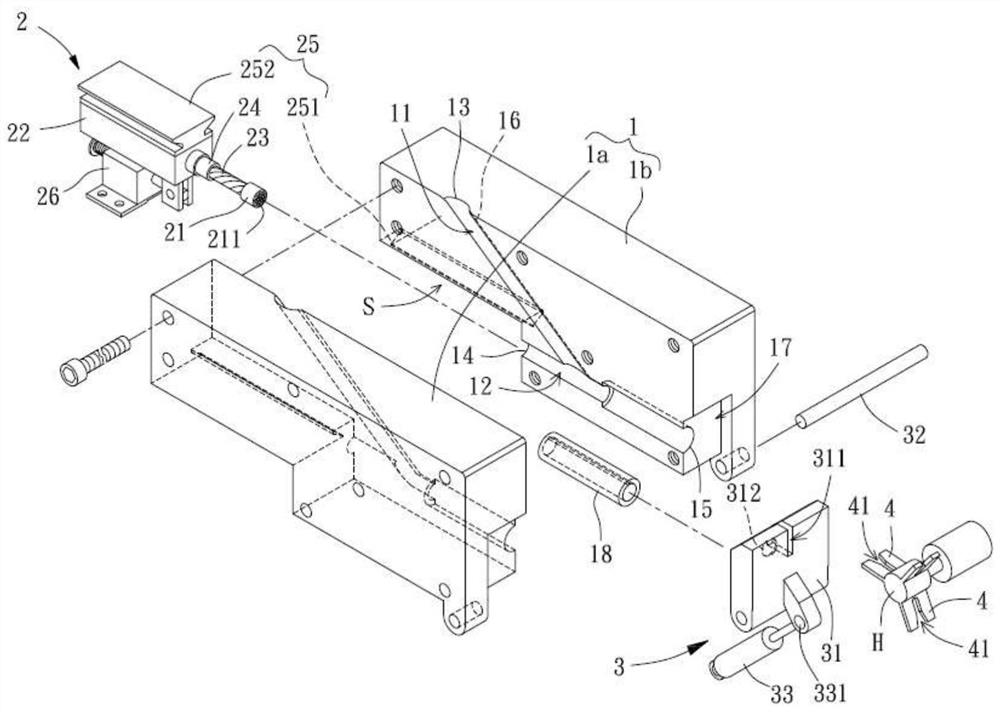
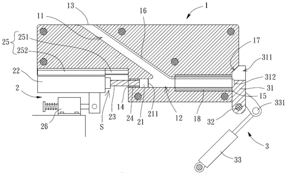
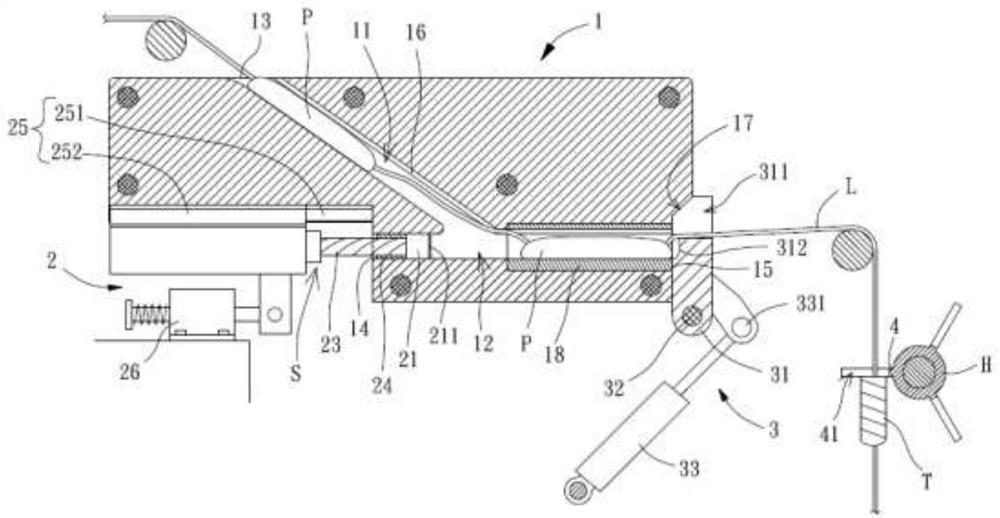
[0042] Please refer to Figures 1 and 2, which is a preferred embodiment of the rotary compression tampon device of the present invention, which includes a mold base 1, a stamping module 2 and a closure assembly 3, the stamping module 2 and the The closing component 3 is movably arranged on the mold base 1 .

[0043] The inside of the mold base 1 has a guide channel 11 and a punching channel 12, the first end of the guide channel 11 has an introduction port 13, the introduction port 13 can be located on the outer surface of the die base 1, the guide The second end of the channel 11 communicates with the punching channel 12 , so that the sliver preform to be compressed is introduced from...


PUM


Abstract

The invention relates to a rotary compression tampon device, which comprises a die holder, a guide channel and a stamping channel are arranged in the die holder, a guide inlet is formed in the first end of the guide channel, the second end of the guide channel is communicated with the stamping channel, and a penetrating inlet and a guide outlet are formed in the two ends of the stamping channel respectively. A wire slot extends from the guide inlet to the guide outlet; a stamping module is provided with a stamping head which penetrates through the penetrating inlet of the stamping channel, and the stamping head is arranged in the stamping channel in a rotary displacement mode; and a sealing assembly is provided with a sealing plate which can seal the guide outlet of the stamping channel in a removable mode.

Description

technical field [0001] The invention relates to a device for manufacturing female sanitary products, in particular to a rotary compression tampon device used in the tampon manufacturing process. Background technique [0002] According to the common catheter-type tampon, it generally includes an auxiliary device and a tampon. The auxiliary device can have a catheter and a push tube. The catheter can be inserted into the female vagina. The front end of the catheter is hemispherical and has a direction The several petals that are stretched out and deformed, the absorbent body of the tampon is located in the conduit, and the push tube can be pushed from the rear end of the absorbent body, so that the several petals are stretched by the absorbent body and placed Insert the appropriate position in the female vagina, and then withdraw the catheter, so that the drawstring of the tampon stays outside the body, and discard the catheter and the push tube. Another relatively simple cat...

Claims


Application Information

Patent Timeline
Patent Type & Authority Applications(China)
IPC IPC(8): A61F13/20
CPCA61F13/202A61F13/2022A61F13/2085A61F13/2088
Inventor 吴静茹
Owner 吴静茹
Why Eureka
Try Eureka