
Lower discharging scraper centrifugal machine

A centrifuge and scraper technology, applied in centrifuges and other directions, can solve the problems of high use and maintenance costs, complex structure, easy vibration, etc., and achieve the effects of reducing equipment costs, simplifying scraper mechanism, and reducing the height of the drum

Pending Publication Date: 2021-08-13
苏州盛天力离心机制造有限公司
View PDF0 Cites 0 Cited by
  • Summary
  • Abstract
  • Description
  • Claims
  • Application Information

AI Technical Summary

Problems solved by technology

Its advantage is a high degree of automation, but its disadvantages are complex structure, easy vibration, high cost of use and maintenance

Method used


Image

  • Lower discharging scraper centrifugal machine
  • Lower discharging scraper centrifugal machine
  • Lower discharging scraper centrifugal machine

Examples


Embodiment Construction

[0018] Specific embodiments of the present invention will be described in detail below in conjunction with the accompanying drawings.

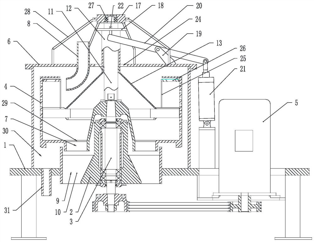
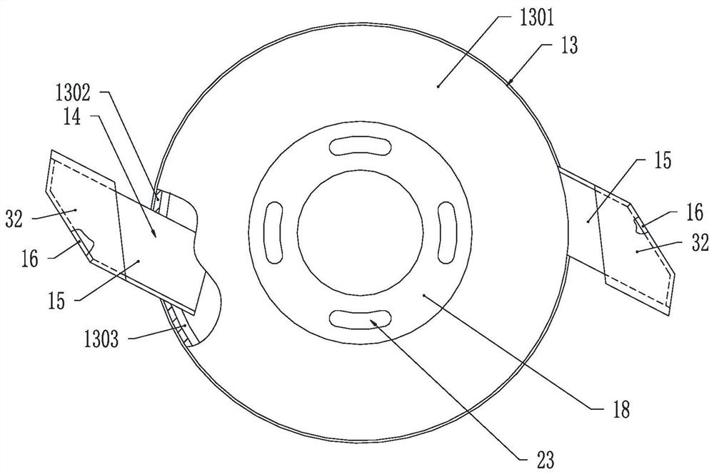
[0019] Such as Figure 1~Figure 4 As shown, the bottom discharge scraper centrifuge includes a base 1, a shaft seat 2 vertically arranged on the base 1, a rotating shaft 3 that is rotatably connected in the shaft seat 2 and both ends protrude from the shaft seat 2, a connecting shaft The drum 4 at the upper end of the rotating shaft 3, the driving device 5 connected to the lower end of the rotating shaft 3 for driving the rotating shaft 3 to rotate, the casing 6 connected to the base 1 and covering the rotating drum 3, and the casing 6 connected to the Feed pipe 8, the lower end of feed pipe 8 is inserted into the drum 4, and the upper end protrudes outside the casing 6. An annular liquid storage chamber 30 is formed between the drum 4 and the casing 6. The base 1 is provided with a The discharge pipe 31 connected to the liquid chamber 30, a ...


PUM


Abstract

The invention relates to a lower discharging scraper centrifugal machine which comprises a base, a shaft seat, a rotating shaft, a rotary drum, a driving device, a machine shell and a feeding pipe. A discharging opening is formed in the center of the bottom face of the rotary drum, a discharging hole corresponding to the discharging opening is formed in the base, the upper end of the rotating shaft is coaxially connected with a lifting limiting column, the lifting limiting column is slidably sleeved with a lifting sleeve, the lower end of the lifting sleeve is connected with a closed cover, the upper end of the lifting limiting column is connected with a limiting ring, the top end of the lifting sleeve is connected with a positioning ring, a supporting arm is fixedly connected onto the machine shell, a swing rod is rotatably connected onto the supporting arm, one end of the swing rod extends to the two sides of the lifting sleeve below the positioning ring, the other end of the swing rod is connected with a piston cylinder connected onto the base, the piston cylinder drives the swing rod to swing in the vertical plane, the end, close to the lifting sleeve, of the swing rod is fixedly connected with a vertically-arranged positioning pin, a positioning hole corresponding to the positioning pin is formed in the positioning ring, and the positioning pin can be inserted into the positioning hole along with upward swing of the swing rod.

Description

technical field [0001] The invention belongs to the technical field of solid-liquid separation equipment, and in particular relates to a bottom discharge scraper centrifuge. Background technique [0002] In the centrifuge separation process of MSG products, the monosodium glutamate industry generally chooses a centrifuge with automatic scraper bottom discharge. During the slow rotation process, the centrifuge scrapes off the filter cake (monosodium glutamate) through the lift and rotation of the scraper. The lifting and rotating drive of the scraper is completed by the lifting mechanism, the rotating mechanism, the corresponding lifting cylinder and the rotating cylinder. [0003] In the process of scraping off the filter cake (monosodium glutamate), there is also a conical closed cover driven by a cylinder for lifting movement to cooperate with scraping. When the closing cover rises, the discharge port at the bottom of the drum is exposed, and then the lifting and rotating...

Claims


Application Information

Patent Timeline
IPC IPC(8): B04B11/08B04B11/05
CPCB04B11/05B04B11/08B04B2011/086
Inventor 陈志才
Owner 苏州盛天力离心机制造有限公司
Learn More