Novel quay crane energy-saving lifting device

A technology of hoisting device and quay bridge, which is applied in the direction of hoisting equipment braking device, hoisting device, crane, etc., to achieve the effects of compact structure layout, reduced operating cost and simple structure

Pending Publication Date: 2022-07-29
华电蓝科科技股份有限公司
View PDF0 Cites 0 Cited by
  • Summary
  • Abstract
  • Description
  • Claims
  • Application Information

AI Technical Summary

Problems solved by technology

[0005] The purpose of the present invention is to provide a new type of energy-saving lifting device for quay cranes, which solves the connection problem between the energy-saving system and the lifting system in the existing quay crane system, and realizes the energy-saving effect when the quay crane device takes off and lands

Method used


Image

  • Novel quay crane energy-saving lifting device
  • Novel quay crane energy-saving lifting device
  • Novel quay crane energy-saving lifting device

Examples


Embodiment 1

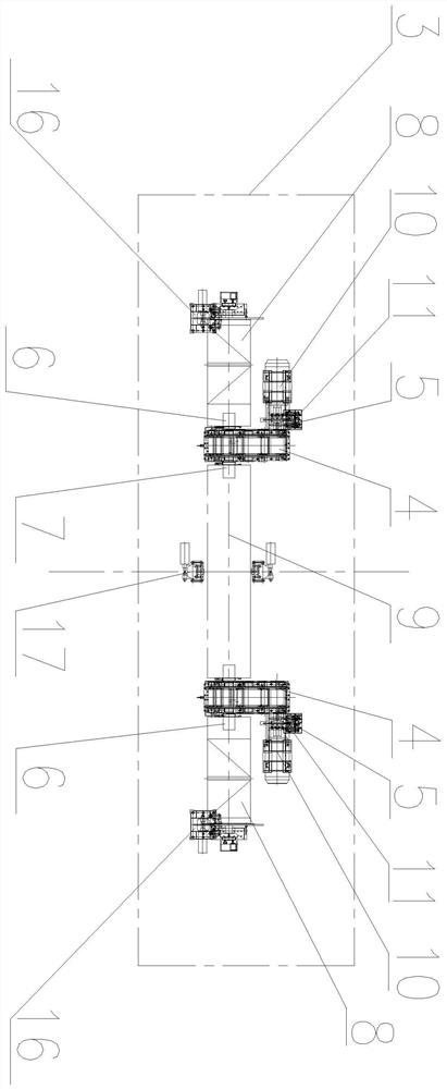
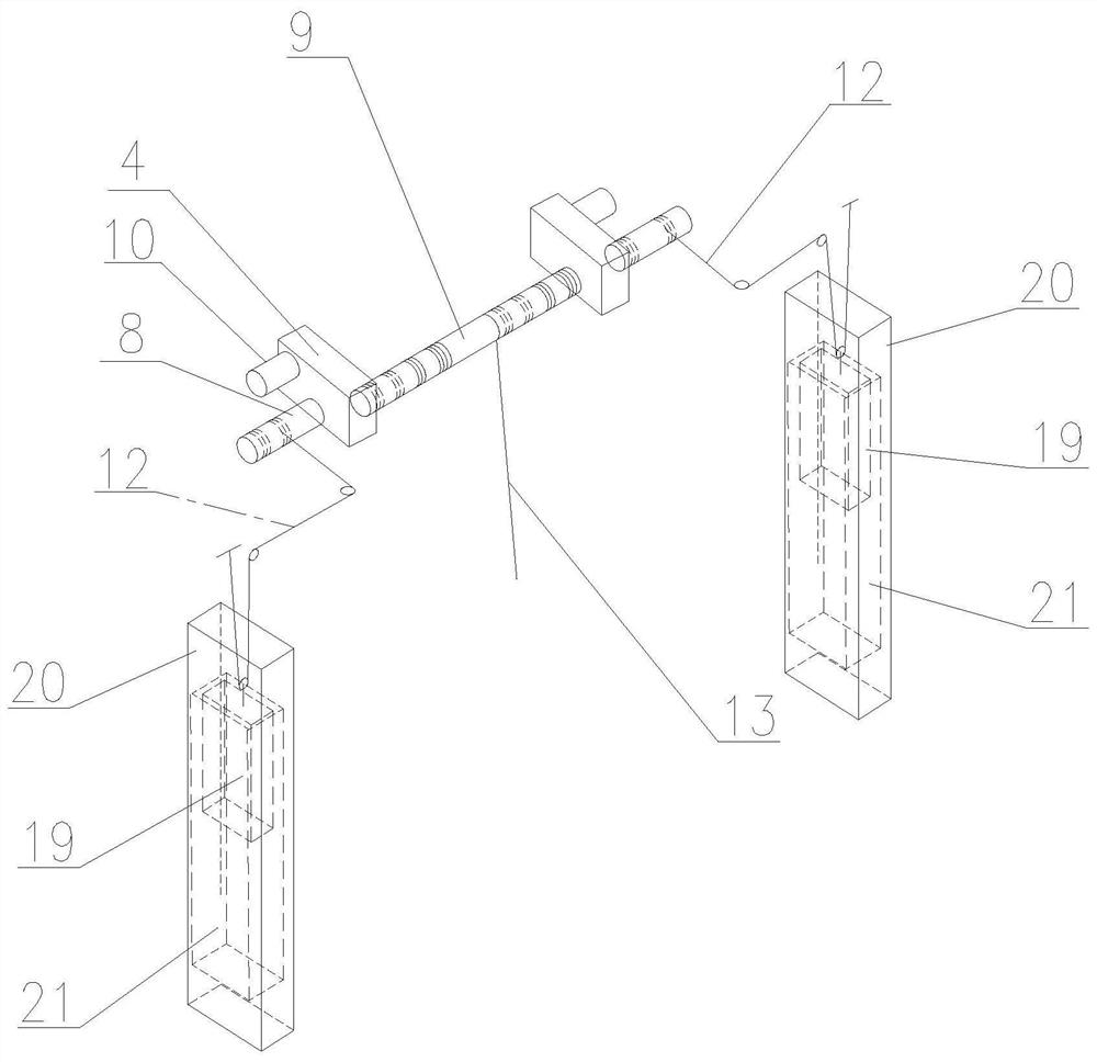
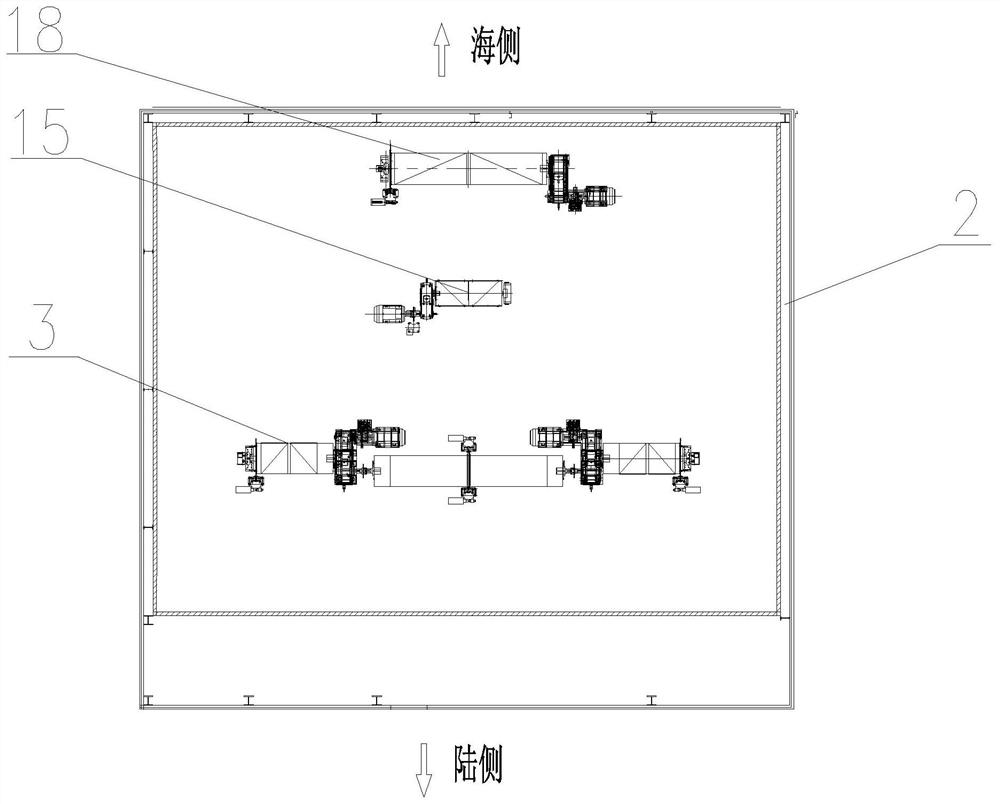
[0026] Embodiment 1 of the present invention: a new type of energy-saving hoisting device for quay cranes, which is arranged on the quay crane device 1, and the new type of energy-saving hoisting device for quay cranes is arranged on the hoisting device 3 in the quay crane machine room 2. The lifting device 3 includes two symmetrically arranged reduction boxes 4, and the reduction box 4 is provided with an input shaft 5, a first output shaft 6 and a second output shaft 7, and the input shaft 5 and the first output shaft 6 are on the same side The lifting device 3 also includes a motor device 10 connected with the input shaft 5 of the reduction box 4, and a first drum 8 connected with the first output shaft 6 of the reduction box 4. The two symmetrically arranged A second drum 9 is arranged between the reduction boxes 4 , and both ends of the second drum 9 are respectively connected with the second output shafts 7 of the two symmetrically arranged reduction boxes 4 .

Embodiment 2

[0027] Embodiment 2 of the present invention: a new type of energy-saving hoisting device for quay cranes, which is arranged on the quay crane device 1, and the new type of energy-saving hoisting device for quay cranes is arranged on the hoisting device 3 in the quay crane machine room 2. The lifting device 3 includes two symmetrically arranged reduction boxes 4, and the reduction box 4 is provided with an input shaft 5, a first output shaft 6 and a second output shaft 7, and the input shaft 5 and the first output shaft 6 are on the same side The lifting device 3 also includes a motor device 10 connected with the input shaft 5 of the reduction box 4, and a first drum 8 connected with the first output shaft 6 of the reduction box 4. The two symmetrically arranged A second drum 9 is arranged between the reduction boxes 4 , and both ends of the second drum 9 are respectively connected with the second output shafts 7 of the two symmetrically arranged reduction boxes 4 . Further, t...

Embodiment 3

[0028]Embodiment 3 of the present invention: a new type of energy-saving hoisting device for quay cranes, which is arranged on the quay crane device 1, and the new type of energy-saving hoisting device for quay cranes is arranged on the hoisting device 3 in the quay crane machine room 2. The lifting device 3 includes two symmetrically arranged reduction boxes 4, and the reduction box 4 is provided with an input shaft 5, a first output shaft 6 and a second output shaft 7, and the input shaft 5 and the first output shaft 6 are on the same side The lifting device 3 also includes a motor device 10 connected with the input shaft 5 of the reduction box 4, and a first reel 8 connected with the first output shaft 6 of the reduction box 4. The two symmetrically arranged A second drum 9 is arranged between the reduction boxes 4 , and both ends of the second drum 9 are respectively connected with the second output shafts 7 of the two symmetrically arranged reduction boxes 4 . Further, th...


PUM


Abstract

The invention discloses a novel quay crane energy-saving lifting device which is arranged on a quay crane device, the novel quay crane energy-saving lifting device is arranged in a quay crane machine room, the lifting device comprises two reduction gearboxes which are symmetrically arranged, and each reduction gearbox is provided with an input shaft, a first output shaft and a second output shaft. A second winding drum is arranged between the two symmetrically-arranged reduction gearboxes, and the two ends of the second winding drum are connected with second output shafts of the two symmetrically-arranged reduction gearboxes respectively. The structure is simpler, the lifting device comprising the two reduction gearboxes which are symmetrically arranged, the first winding drum and the second winding drum is arranged in the machine room, and the lifting device is connected with the balance weight part through the balance weight steel wire rope arranged on the first winding drum and the lifting steel wire rope arranged on the second winding drum; therefore, the purpose of counteracting the weight of a part of the trolley lifting appliance and goods by using the counterweight piece is achieved. The purposes of saving energy and reducing consumption can be achieved, and the operation cost of the quay crane system can be reduced.

Description

technical field [0001] The invention relates to a novel energy-saving hoisting device for quay cranes, belonging to the technical field of quay crane equipment. Background technique [0002] As the key loading and unloading equipment of container terminals, quay cranes operate frequently and consume a large amount of energy. Reducing the energy consumption of quay cranes is an urgent need of ports. For the energy-saving technology of quay cranes, there are many ways to reduce power consumption equipment and reduce the operating parameters of quay cranes, but all of them will have a certain impact on the normal use and efficiency of quay cranes. Some technologies adopt the energy-saving counterweight technology. One is to directly connect the heavy objects and the counterweight through the wire rope to offset part of the weight and achieve the purpose of energy saving. However, the wire rope winding is complicated, and a separate set of wire ropes needs to be set up. The layo...

Claims


Application Information

Patent Timeline
Patent Type & Authority Applications(China)
IPC IPC(8): B66C19/00B66C5/02B66C13/00B66C11/04
CPCB66C19/007B66C5/02B66C13/00B66C11/04
Inventor 赵迎九肖强谢文宗石鑫刘江浩曹磊王泽宇初柳辰郑雪峰
Owner 华电蓝科科技股份有限公司
Why Eureka
Try Eureka