
Asymmetric Aeration Method for Curved Spillways

A spillway, asymmetrical technology, applied in sea area engineering, construction, barrage/weir, etc., to save engineering cost, improve the effect of excessive water surface gradient in bends, and simple construction structure

Active Publication Date: 2020-08-04
SICHUAN UNIV
View PDF3 Cites 0 Cited by
  • Summary
  • Abstract
  • Description
  • Claims
  • Application Information

AI Technical Summary

Problems solved by technology

At present, there are no effective measures to specifically address the problem of cavitation damage in bends and at the same time effectively improve the unfavorable flow conditions such as excessive water surface drop in bends

Method used


Image

  • Asymmetric Aeration Method for Curved Spillways
  • Asymmetric Aeration Method for Curved Spillways
  • Asymmetric Aeration Method for Curved Spillways

Examples


Embodiment 1

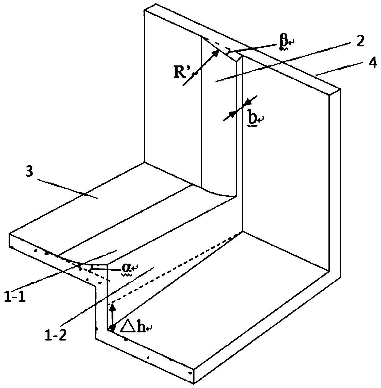
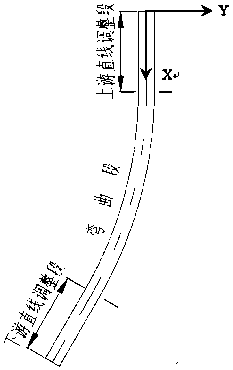
[0029] A spillway is open layout, the turning radius of the curved section is 250m, and the turning angle θ=30°. The spillway has the same width throughout, the width is 10m, and the height of the left and right side walls is about 14m. A 50m straight line adjustment section tangent to the curved section is set upstream of the curved section, and the slope of the bottom plate is i=12°. Using the asymmetric aeration method, the aeration facilities formed are as follows: figure 1 shown. Specifically, an aeration sill 1 is set on the upstream square floor of the curved initial section of the curved spillway, and the aeration sill is connected to the downstream end of the sill by an arc-shaped sill 1-1 that is tangent to the bottom plate 3 of the spillway along the flow direction. The falling sill 1-2 constitutes, and the arc-shaped lateral foot 2 is set on the spillway concave bank wall 4 corresponding to the aeration sill, so that the cross-sectional width of the water flow ch...

Embodiment 2

[0035] The spillway is an open layout, the turning radius of the curved section is 280m, the turning angle θ=30°, there is a 50m straight line adjustment section tangent to the curved section upstream of the curved section, and the slope of the bottom plate is i=9°. The spillway has the same width throughout, the width is 10m, and the height of the left and right side walls is about 15m. Adopt the method with embodiment 1, the aeration facility structure of design is identical, and difference is that each parameter is as follows:

[0036] The aerated sill has an angled bend of α=8°, the height of the concave bank aerated sill from the bottom plate is 2.5m, and the height of the convex bank aerated sill from the bottom plate is 4m. The curved section adopts an inclined floor, and the height difference △h between the edge of the concave bank of the floor and the edge of the convex bank is 1.5m. The angle between the lateral foot of the concave bank and the wall of the concave b...


PUM


Abstract

The invention provides an asymmetric aeration method suitable for a curving spillway. An aerator is arranged on an upstream square bottom plate of the bending starting section of the curving spillway,the aerator is composed of an arc up sill tangent with a spillway bottom in the water flow direction and a drop sill connected with the downstream end of the up sill, a side attaching foot is arranged at the position, corresponding to the aerator, on the spillway concave side wall, the width of the section of the water flow channel is subject to certain shrinkage in the water flow direction, andwhen the water flow flows through, the stable side aeration cavity is formed. Meanwhile, the water flow flows through the drop sill, and a stable bottom aeration cavity is formed; the side aeration cavity is communicated with the bottom aeration cavity; through the method, the cavitation damage of the curving spillway can be avoided; due to the fact that the aerator has the enough side cavity andthe bottom cavity, a gas well does not need to be built, the construction structure is simple, and the engineering cost is low; in addition, the side attaching foot forces the water flow to be subjectto steering, and the water flow is consciously thrown to the convex side; the method is used in combination with a common channel bottom ultra-high method in the engineering, and the phenomenon thatthe spillway water face gradient is too large is effectively avoided.

Description

technical field [0001] The invention belongs to the field of water discharge structures of hydropower projects, in particular to an aeration method for a curved spillway. Background technique [0002] In water conservancy and hydropower projects, it is usually necessary to arrange drainage structures to vent the flood that cannot be accommodated by the planned reservoir, so as to ensure the safety of the dam body itself. With the development of water conservancy and hydropower engineering construction, high-dam large single-width flow projects are becoming more and more common, and the problem of high-speed water flow is also becoming more and more significant. Cavitation damage often occurs in some parts where the geometric shape of high-head discharge structures changes, such as the shrinkage part of the entrance section of the flood discharge tunnel, the side wall behind the gate slot, and the turning section of the tunnel. [0003] In conventional engineering applicatio...

Claims


Application Information

Patent Timeline
Patent Type & Authority Patents(China)
IPC IPC(8): E02B8/06
CPCE02B8/06
Inventor 刁明军官夏菲路信王磊蒋雷任昱汪厚松
Owner SICHUAN UNIV
Learn More