A cavitation facility for a stepped overflow dam

An overflow dam and ladder technology, which is applied in sea area engineering, construction, barrage/weir, etc., to achieve the effects of simple construction, accelerated dissipation, and reduced possibility of cavitation damage

Active Publication Date: 2020-04-03
KUNMING UNIV OF SCI & TECH
View PDF2 Cites 0 Cited by
  • Summary
  • Abstract
  • Description
  • Claims
  • Application Information

AI Technical Summary

Problems solved by technology

[0004] The invention provides an anti-cavitation facility for a stepped overflow dam, which is used to solve the problem that cavitation occurs at the junction of the first step elevation and the overflow dam surface

Method used


Image

  • A cavitation facility for a stepped overflow dam
  • A cavitation facility for a stepped overflow dam
  • A cavitation facility for a stepped overflow dam

Examples


Embodiment 1

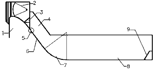
[0026] Example 1: A cavitation facility 5 for a stepped overflow dam is applied to a key water conservancy and hydropower project. The length of the dam crest of the power station is 482 m, the maximum dam height is 132 m, and the single-width flow rate is 150-200 m 3 / s·m in flood discharge and energy dissipation buildings. The flood discharge and energy dissipation structure is composed of the overflow surface hole on the left bank and the flood discharge sand bottom hole. The number of overflow surface holes is 5 holes, and the size of the hole is 13m×20m. It adopts "wide tail pier + ladder + stilling pool" The integrated flood discharge and energy dissipation method adopts the WES weir type, followed by a slope section of 1:0.75, with a total of 29 steps on the dam surface, the steps are 1 m high and 0.75 m wide, and the slope of the dam surface is 53°. and stilling pool.

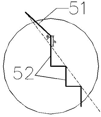
[0027] Its structure is as Figure 6 Shown: including the sill 51 set behind the wide tail pier 3 ...

Embodiment 2

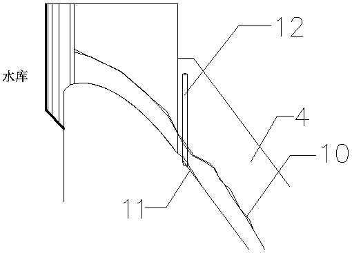
[0030] Example 2: A cavitation facility 5 for a stepped overflow dam is applied to a key water conservancy and hydropower project. The length of the dam crest of the power station is 482 m, the maximum dam height is 132 m, and the single-width flow rate is 100-150 m 3 / s·m in flood discharge and energy dissipation buildings. The flood discharge and energy dissipation structure is composed of the overflow surface hole on the left bank and the flood discharge sand bottom hole. The number of overflow surface holes is 5 holes, and the size of the hole is 13m×20m. It adopts "wide tail pier + ladder + stilling pool" The integrated flood discharge and energy dissipation method adopts the WES weir type, followed by a slope section of 1:0.75, with a total of 29 steps on the dam surface, the steps are 1 m high and 0.75 m wide, and the slope of the dam surface is 53°. and stilling pool.

[0031] Its structure is as Figure 7 , Figure 8 Shown: include the pick-up 51 and the novel tran...


PUM


Abstract

The invention discloses an anti-cavitation facility of a stepped overflow dam. According to the anti-cavitation facility of the stepped overflow dam, a flaring pier is used for increasing the compression capacity on the water flow, the discharged water flow is transversely contracted and vertically stretched, and the discharged water flow is ejected to the downstream. Stranded ejection water tongues aerate and collide with each other in the air, so that energy is dissipated; in addition, a flip bucket arranged at the tail of the flaring pier can lift the discharged water flow away from the overflow surface, an aeration cavity is formed. An anti-cavitation transition step is utilized to mix outside air into the cavity, so that the negative pressure at the junction of the flip bucket and thetransition step is greatly reduced, the aeration concentration in the step is improved, and the possibility of cavitation damage is reduced. The step behind the cavity happens to be the drop point ofthe front edges of the water tongues, and the friction effect of the step on the water flow is utilized to accelerate the dissipation of the step on the discharge energy; after that, a reverse arc section and a stilling basin are utilized for further energy dissipation. The anti-cavitation facility of the stepped overflow dam utilizes a combined flood discharge energy dissipation structure with section partition and region partition, cavitation damage on the overflow dam surface is reduced, and the energy dissipation rate is improved.

Description

technical field [0001] The invention relates to an anti-cavitation facility for a stepped overflow dam, which belongs to the field of anti-cavitation ventilation for steps with high water head and large single-width flow. Background technique [0002] It is a characteristic of high dam construction in my country that the single-width discharge of flood discharge is increasing, and it is also the development trend of high dam construction in the future. The Tuoxi Hydropower Station built in the 1960s has a single-width discharge of 143.2 m 3 (s m), the Ankang Hydropower Station built in the 1970s had a maximum single-width discharge of 282.7 m 3 (s m), as for some water conservancy projects from the 1990s to the present, the single-width discharge has increased even more. Although increasing the single-width flow of flood discharge can reduce the project cost, it may also cause cavitation and cavitation problems in the flood discharge structures of high dams. Judging from ...

Claims


Application Information

Patent Timeline
Patent Type & Authority Patents(China)
IPC IPC(8): E02B8/00E02B8/06
CPCE02B8/00E02B8/06
Inventor 董丽艳杨具瑞
Owner KUNMING UNIV OF SCI & TECH
Why Eureka
Try Eureka