Linear actuator with compact structure

A technology of linear actuators and worm gears, applied in transmissions, transmission parts, belts/chains/gears, etc., can solve the problem of high internal space requirements of linear actuators, many planetary gear components and bulky internal structures and other problems, to achieve the effect of compact assembly structure, small space occupation and good positioning effect

Pending Publication Date: 2018-09-11
NINGBO HAISHIKAI DRIVER TECH CO LTD
View PDF0 Cites 2 Cited by
  • Summary
  • Abstract
  • Description
  • Claims
  • Application Information

AI Technical Summary

Problems solved by technology

[0003] The existing linear actuators on the market, in order to improve the transmission torque, have developed a structure in which a planetary gear assembly is installed on the worm wheel and the screw rod, but the assembly of the planetary gear assembl

Method used


Image

  • Linear actuator with compact structure
  • Linear actuator with compact structure
  • Linear actuator with compact structure

Examples


Example Embodiment

[0035] Embodiment one

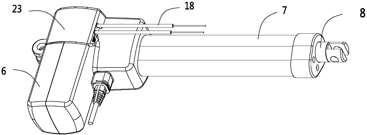
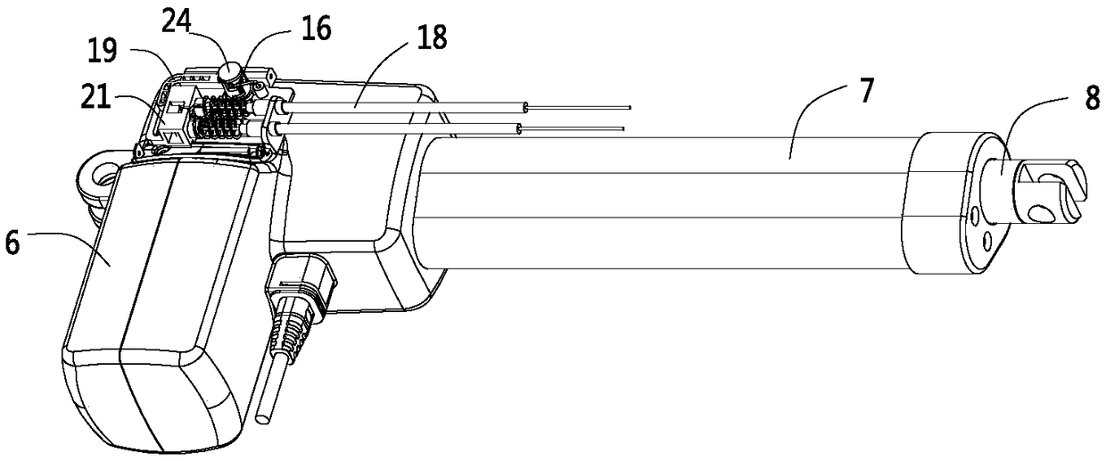
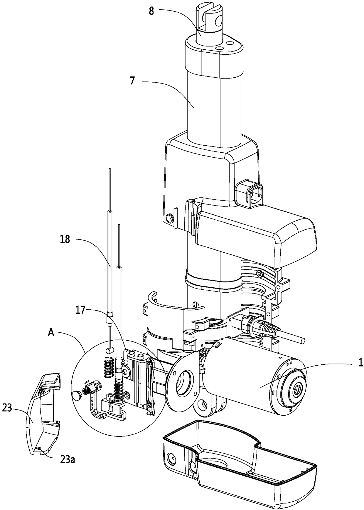
[0036] like Figure 1 to Figure 9 As shown, this embodiment is a compact linear actuator. In this embodiment, the linear actuator includes a drive motor 1, a drive worm 2, a worm wheel 3, a screw 4, and a nut 5. The drive motor 1 is connected to the drive worm 2. The drive worm 2 drives the worm wheel 3 to rotate, the worm wheel 3 rotates to drive the screw 4 to rotate, and the screw 4 rotates to drive the nut 5 to move axially. In addition, this embodiment also includes a casing 6, an outer tube 7, and an inner tube 8. The nut 5 is connected to the inner tube 8, the outer shell 6 is connected to the outer tube 7, the driving motor 1 is fixedly installed in the outer shell 6, and the axial movement of the nut 5 is finally expressed as an axial relative displacement between the inner tube 8 and the outer tube 7 .

[0037] In this embodiment, a planetary gear assembly is also provided between the worm wheel 3 and the screw rod 4, for details, please ref...

Example Embodiment

[0088] Embodiment two

[0089]The difference between this embodiment and Embodiment 1 is that, in the first embodiment, a brake worm is used to brake the inner ring gear. A suit of an inner ring gear outer torsion spring, directly pulls the inner ring gear outer torsion spring through the cable to realize the radial contraction or radial expansion of the inner ring gear outer torsion spring, when the inner ring gear outer torsion spring radially contracts , will brake the ring gear, which is an alternative to the brake in the first embodiment.

Example Embodiment

[0090] Embodiment three

[0091] The difference between this embodiment and Embodiment 1 is that the structure of the one-way locking coupling between the worm and the screw is different. In this embodiment, the transmission torsion spring is set between the first dial and the second dial In the sheet, the damping ring is set in the transmission torsion spring. In other words, the damping ring is located on the innermost side, the first paddle and the second paddle are located on the outermost side, and the transmission torsion spring is located on the damping ring and the first paddle. , between the second paddle.

[0092] The bending pins of the transmission torsion spring in this embodiment are bent radially outward. When the first paddle transmits torque to the transmission torsion spring, the bending pins are moved in the direction of loosening the transmission torsion spring. And when the second paddle transmits torque to the transmission torsion spring, the bent pin is...


PUM


Abstract

The invention discloses a linear actuator with a compact structure, and belongs to the technical field of linear transmission. The linear actuator with the compact structure comprises a transmission worm, a worm wheel, a lead screw and a nut. The transmission worm drives the worm wheel to rotate, the worm wheel rotate to drives the lead screw to rotate, and the lead screw rotate to drives the nutto move axially. A planetary gear assembly is arranged between the worm wheel and the lead screw, the planetary gear assembly comprises an inner gear ring, a sun gear, a planetary gear, and a planet carrier, the sun gear and the worm wheel rotate synchronously, and the planet carrier and the lead screw rotate synchronously. The linear actuator further includes a supporting seat arranged on one side of the rear end of the planetary gear assembly, a first sliding sleeve is installed on the supporting seat in a sleeving mode, a first limiting blocking ring is arranged at the tail end of the firstsliding sleeve, and the sun gear is installed in the first sliding sleeve in a sleeving mode and located between the first limiting blocking ring and the planet carrier or the lead screw. The linearactuator with the compact structure has the advantages of enabling the internal structure of the linear actuator to be more compact and less in occupied space.

Description

【Technical field】 [0001] The invention relates to a compact linear actuator and belongs to the technical field of linear transmission. 【Background technique】 [0002] Linear actuators, also known as electric push rods, are widely used in furniture, medical equipment, solar power generation, etc. The main structure includes a drive motor, a drive worm, a worm wheel, a screw, and a nut. The working principle is that the drive motor drives the drive worm Rotation, the transmission worm meshes with the worm wheel to drive the worm wheel to rotate, the worm wheel to drive the screw to rotate, the screw to rotate to drive the nut to move axially, the nut is generally connected to the inner tube, so as to realize the telescopic movement of the inner tube. [0003] The existing linear actuators on the market, in order to improve the transmission torque, have developed a structure in which a planetary gear assembly is installed on the worm wheel and the screw rod, but the assembly of...

Claims


Application Information

Patent Timeline
IPC IPC(8): F16H37/12F16H57/023F16H57/021
CPCF16H37/12F16H57/021F16H57/023
Inventor 翟鑫
Owner NINGBO HAISHIKAI DRIVER TECH CO LTD
Why Eureka
Try Eureka