Fuel gas plug valve
A gas cock valve and valve body technology, which is applied to the cock, valve details, valve device and other directions including the cut-off device, can solve the problems of inconvenient ignition of the gas stove, and achieve the effects of reducing time difference, convenient operation, and flexible installation position
- Summary
- Abstract
- Description
- Claims
- Application Information
AI Technical Summary
Problems solved by technology
Method used
Image

Examples
Embodiment 1
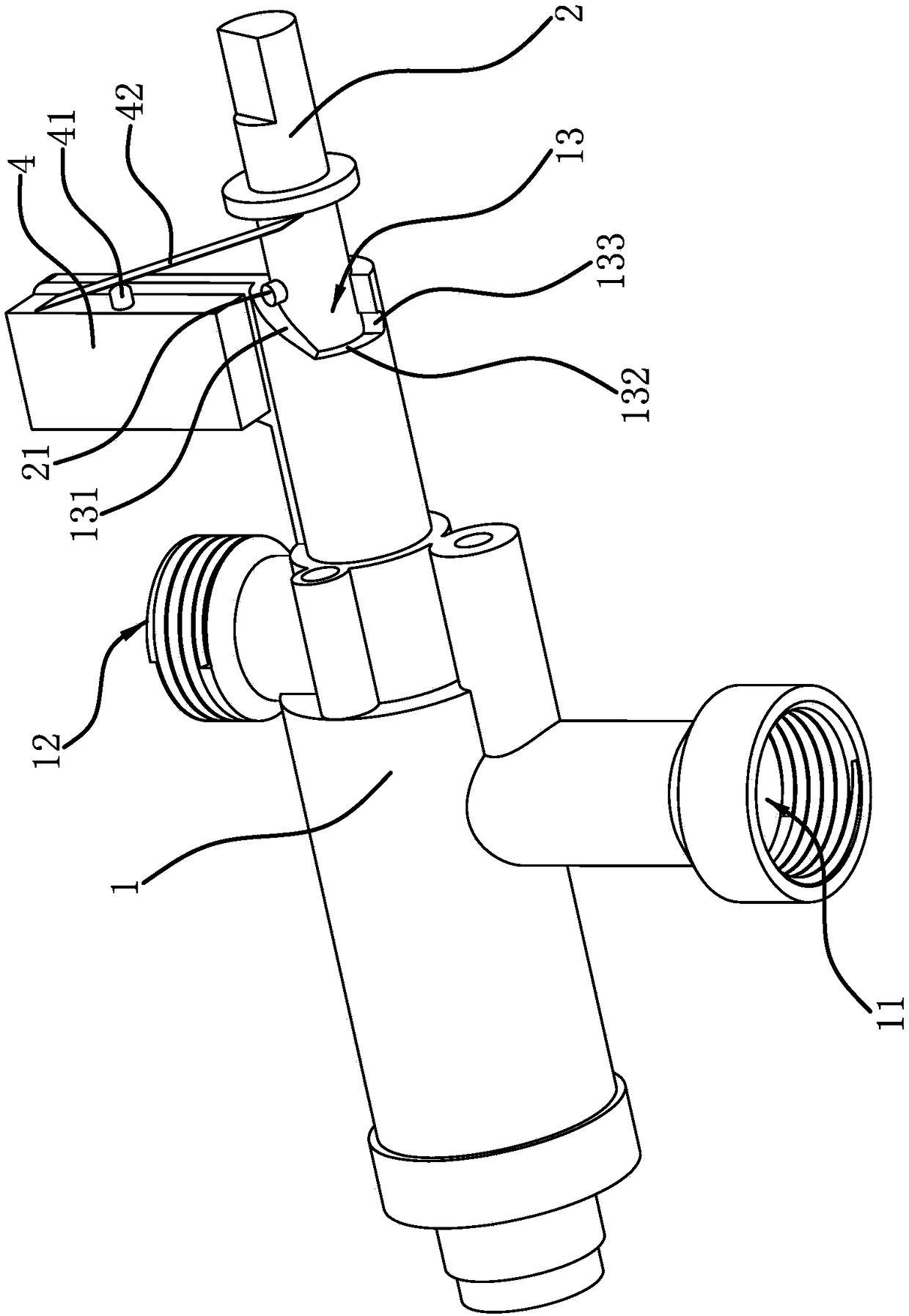
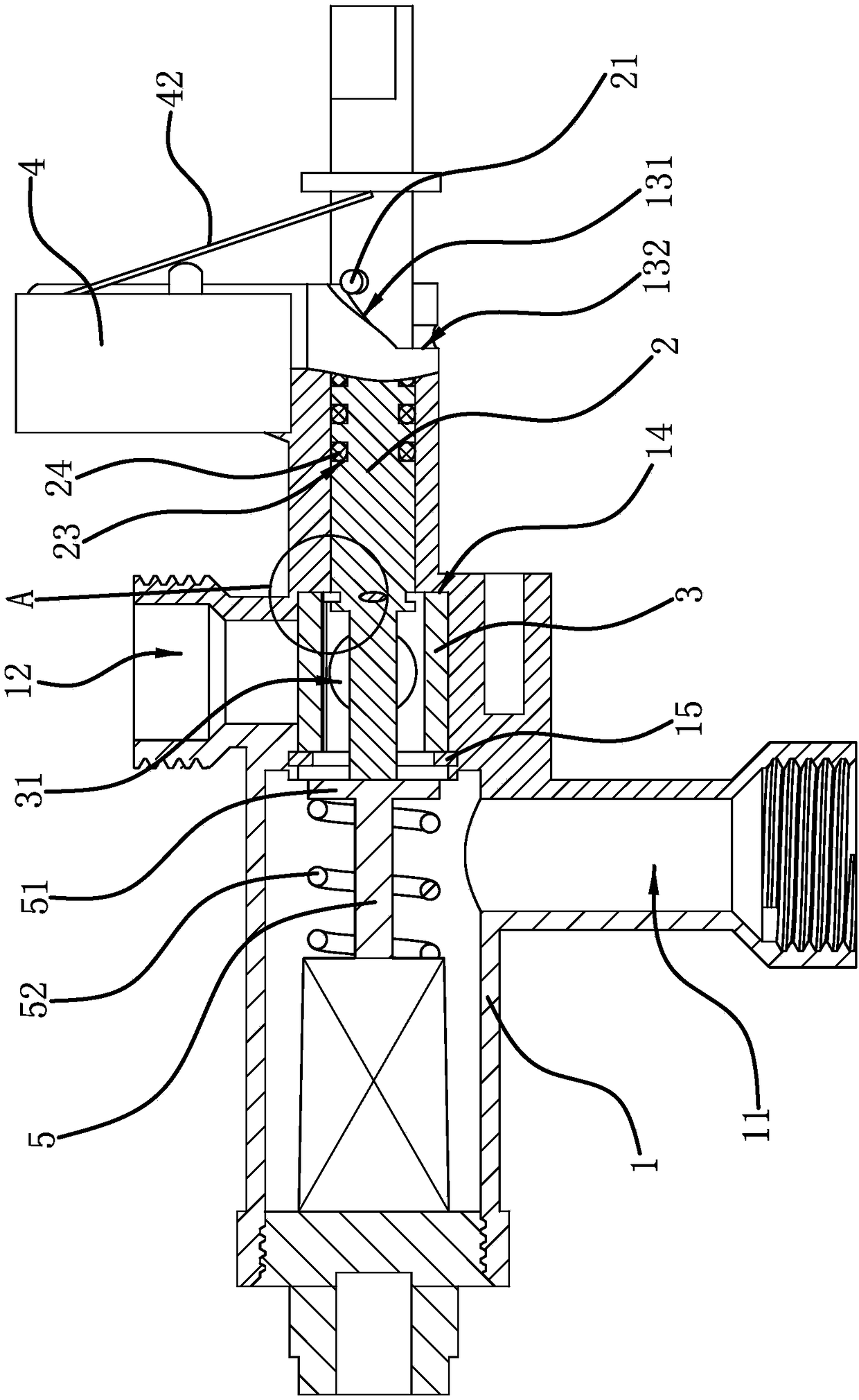
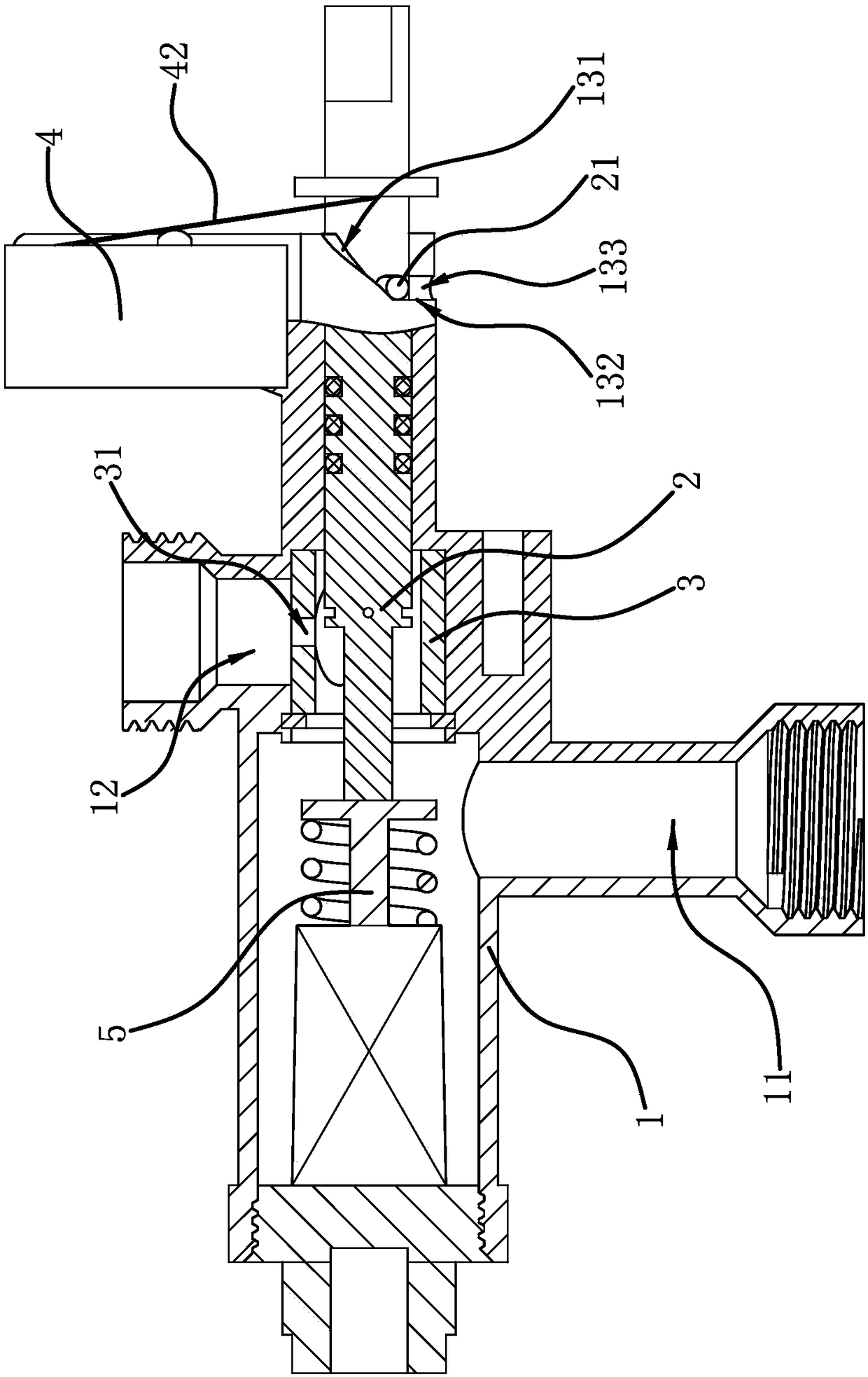
[0033] Such as figure 1 As shown, a gas cock valve includes a valve body 1, the valve body 1 is tubular, and has an air inlet 11 and an air outlet 12 on the side wall of the valve body 1, and the direction of the air inlet 11 and the air outlet 12 is opposite. One end of the valve body 1 is plugged with a valve stem 2, the valve stem 2 can rotate in the circumferential direction and slide axially relative to the valve body 1, and an ignition switch 4 is fixed on the valve body 1, the ignition switch 4 is a jog switch , with a button 42 and a shrapnel 41 capable of pressing the button 42, a relief notch 13 is also provided on the end face of the valve body 1, the relief notch 13 is flared, and the side walls of the relief notch 13 are opposite to each other. The bottom surface is inclined to form a pushing slope 131. The bottom surface of the gap 13 is a guide plane 132. On the other side wall of the gap 13, a positioning groove 133 is provided. One end of the guiding plane 132...
Embodiment 2
[0037] The structure of the gas cock valve is basically the same as that of Embodiment 1, the difference is that Figure 6 As shown, the relief notch 13 is set on the side wall of the valve stem 2, and the pushing slope 131 is also the inclined side wall of the relief notch 13, and the protrusion 21 is located on the inner wall of the port of the valve body 1. At this time, pressing the valve stem 2. The pushing inclined surface 131 can abut against the protruding head 21, so that the valve stem 2 can rotate at a set angle.
Embodiment 3
[0039] The structure of the gas cock valve is basically the same as that of Embodiment 1, the difference is that Figure 7 As shown, there is a boss 16 on the end surface of the valve body 1, and there is a pushing slope 131 on the boss 16. The pushing slope 131 is inclined relative to the end surface of the valve body 1, and the valve stem 2 has a convex head 21. When the valve stem 2 is pressed into the valve body 1 so that the ignition switch 4 is turned on, the protrusion 21 can slide along the pushing slope 131 so that the valve core 3 can rotate and open. The lower end of the pushing inclined surface 131 is connected with the end surface of the valve body 1, and the end surface of the valve body 1 also has a limiting part 17, and a positioning groove 133 is opened on the limiting part 17, and the notch of the positioning groove 133 has a top facing the boss 16. When one side of the inclined surface 131 is pushed, the valve core 3 is at the maximum opening angle when the ...
PUM
 Abstract
Description
Claims
Application Information
 - Generate Ideas
- Intellectual Property
- Life Sciences
- Materials
- Tech Scout
- Unparalleled Data Quality
- Higher Quality Content
- 60% Fewer Hallucinations
Browse by: Latest US Patents, China's latest patents, Technical Efficacy Thesaurus, Application Domain, Technology Topic, Popular Technical Reports.
© 2025 PatSnap. All rights reserved.Legal|Privacy policy|Modern Slavery Act Transparency Statement|Sitemap|About US| Contact US: help@patsnap.com