Circularly polarized F-P resonant cavity antenna with high gain and low RCS

A resonant cavity antenna, circular polarization technology, applied in the direction of antenna, antenna grounding switch structure connection, electrical components, etc., can solve the problems of increased manufacturing cost, complex antenna feed structure, low gain, etc., to achieve the effect of simplifying the design

Active Publication Date: 2018-09-11
XIDIAN UNIV +1
View PDF2 Cites 22 Cited by
  • Summary
  • Abstract
  • Description
  • Claims
  • Application Information

AI Technical Summary

Problems solved by technology

In 2017, Kun li, Ying Liu and others published an article titled "A Circularly Polarizaed High-Gain Antenna With Low RCS Over a Wideband Using Chessborad Polarization Conversion Metasurface" on the "IEEE Transactions on Antennas and Propagation" Journal Volume 65, Issue 8 The thesis discloses a high-gain and low-RCS circularly polarized antenna, which is composed of four F-P resonant cavity antenna elements that rotate at the center to form an array. Each F-P resonant cavity antenna includes an upper polarization conversion surface and a lower slot antenna. The polarization conversion surface unit adopts a sandwich structure through which the linearly polarized wave can be converted into a circularly polari

Method used


Image

  • Circularly polarized F-P resonant cavity antenna with high gain and low RCS
  • Circularly polarized F-P resonant cavity antenna with high gain and low RCS
  • Circularly polarized F-P resonant cavity antenna with high gain and low RCS

Examples


Embodiment 1

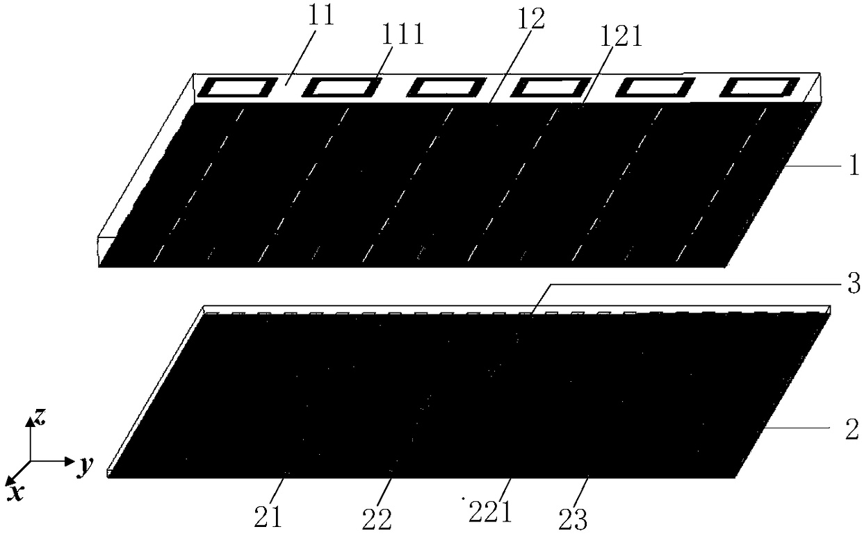
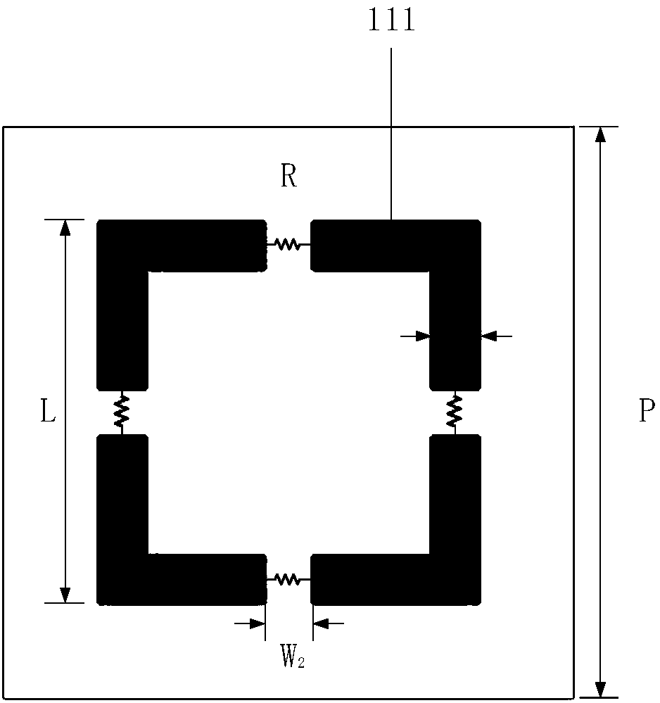
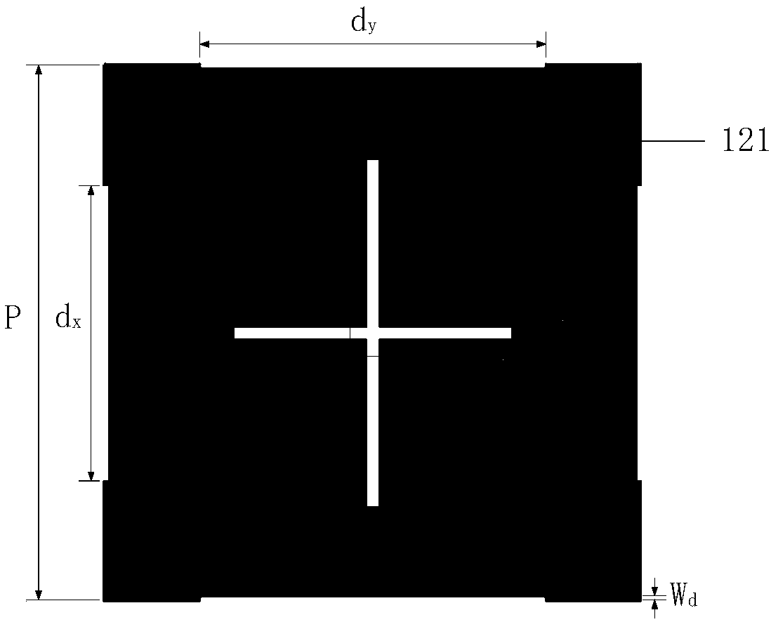
[0031] refer to figure 1 , the present invention includes an upper dielectric board 1 and a lower dielectric board 2, the upper dielectric board 1 has a wave-absorbing surface 11 printed on its upper surface, and a partially reflective surface 12 printed on its lower surface; the wave-absorbing surface 11, A structure of 6×6 wave-absorbing units 111 is periodically arranged. The wave-absorbing unit 111 adopts a square ring structure with a rectangular gap in the middle of the four sides. Each gap is loaded with a resistor to convert electromagnetic wave energy into heat energy, thereby achieving RCS reduction; the partially reflective surface 12 adopts a structure in which 6×6 partially reflective surface units 121 are periodically arranged, and the partially reflective surface unit 121 adopts a cross-shaped groove with different lengths in the center and four sides with The square patch structure with rectangular slots, due to the different lengths of the cross-shaped slots, ...

Embodiment 2

[0039] The structure of this example is the same as that of Example 1, and only the following parameters have been adjusted:

[0040] The distance H=11mm between the lower surface of the upper dielectric plate 1 and the upper surface of the lower dielectric plate 2, the length of the square ring of the absorbing unit 111 is L=7mm, and the ring width is W 1 =0.5mm, the size of the rectangular notch is W 1 ×W 2 =0.5mm×1.5mm, resistance impedance R=50Ω, the length of the long groove of the cross-shaped groove of the partially reflective surface unit 12 is S x =7mm, the length of the short slot is S y =5mm, groove width is W s = 0.2mm, the rectangular grooves arranged on the four sides of the partially reflective surface unit 12 include a pair of rectangular long grooves and a pair of rectangular short grooves, and the length of the rectangular long grooves is d y =6mm, the length of the short rectangular slot is d x =5mm, groove width is W d =0.05mm, the length of the strip...

Embodiment 3

[0042] The structure of this example is the same as that of Example 1, and only the following parameters have been adjusted:

[0043] The distance H=13mm between the lower surface of the upper dielectric plate and the upper surface of the lower dielectric plate, the length of the square ring of the absorbing unit 111 is L=9mm, and the ring width is W 1 = 1.5mm, the size of the rectangular notch is W 1 ×W 2 =1.5mm×0.5mm, resistance impedance R=200Ω, the length of the long groove of the cross-shaped groove of the partially reflective surface unit 12 is S x =9mm, the length of the short slot is S y =7mm, slot width is W s =0.4mm, the rectangular grooves arranged on the four sides of the partially reflective surface unit 12 include a pair of rectangular long grooves and a pair of rectangular short grooves, and the length of the rectangular long grooves is d y =11mm, the length of the short rectangular slot is d x =10mm, slot width is W d =0.2mm, the length of the strip metal...


PUM

PropertyMeasurementUnit
Side lengthaaaaaaaaaa
Thicknessaaaaaaaaaa
Thicknessaaaaaaaaaa

Abstract

The invention provides a circularly polarized F-P resonant cavity antenna with high gain and low RCS, and aims to simplify the structure of the antenna and reduce the manufacturing cost of the antenna. The antenna comprises an upper dielectric plate and a lower dielectric plate, a wave-absorbing surface is printed on the upper surface of the upper dielectric plate, a partial reflection surface isprinted on the lower surface, the wave-absorbing surface comprises N*N wave-absorbing units arranged in a periodic manner, the wave-absorbing units adopt annular patch structures, four edges of the wave-absorbing units are provided with gaps, resistances are loaded on the gaps, the partial reflection surface comprises N*N partial reflection surface units arranged in a periodic manner, the partialreflection surface units adopt square patch structures, the center of each partial reflection surface unit is provided with a cross slot with different length and width, four edges of the partial reflection surface unit are provided with rectangular grooves, a rectangular metal patch is printed on the upper surface of the lower dielectric plate, a floor is printed on the lower surface, the rectangular metal patch and the floor are connected through a coaxial line, and a high-impedance surface formed by an area array formed by periodic arrangement of a plurality of strip-shaped metal patches isprinted around the rectangular patch.

Description

technical field [0001] The invention belongs to the technical field of antennas, in particular to a circularly polarized F-P resonant cavity antenna with high gain and low RCS, which can be used for airborne antennas and radar communications of aircraft. Background technique [0002] In the fields of aircraft airborne antennas, long-distance transmission and base station antennas, it is often required that the antenna has a particularly strong ability to transmit and receive radio signals in a specific direction, and can shield radio signals in other directions as much as possible, so for high-gain directional The requirements for high-performance antennas are getting higher and higher. Miniaturization and light weight are an inevitable trend in the development of modern science and technology, and the antenna is no exception, that is, replace the complex structure with a simple structure as small as possible to achieve the same function. Small and low profile has always be...

Claims


Application Information

Patent Timeline
IPC IPC(8): H01Q1/50H01Q15/14H01Q15/24H01Q17/00H01Q19/10
CPCH01Q1/50H01Q15/145H01Q15/244H01Q17/008H01Q19/104
Inventor 姜文张哲任俊毅龚书喜
Owner XIDIAN UNIV
Why Eureka
Try Eureka