Oil-injection rust-preventing device for mechanical parts

A technology for mechanical parts and cylinder blocks, applied in the field of mechanical anti-rust devices, can solve the problems of high labor intensity, incomplete and incomplete anti-rust, time-consuming and labor-intensive, etc., and achieve good effect of oil injection and anti-rust.

Inactive Publication Date: 2018-09-14
何位桥
View PDF4 Cites 0 Cited by
  • Summary
  • Abstract
  • Description
  • Claims
  • Application Information

AI Technical Summary

Problems solved by technology

[0005] The present invention overcomes the disadvantages of manual oiling of mechanical parts to prevent rust, which is not only labor-intensive, time-consuming and labor-intensive, rust prevention is not comprehensive and thorough, but also unclean and unhygienic, which easily causes workers' bodies to be contam

Method used


Image

  • Oil-injection rust-preventing device for mechanical parts
  • Oil-injection rust-preventing device for mechanical parts
  • Oil-injection rust-preventing device for mechanical parts

Examples


Embodiment 1

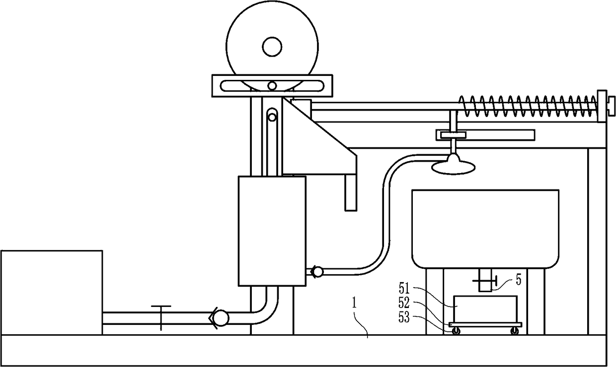
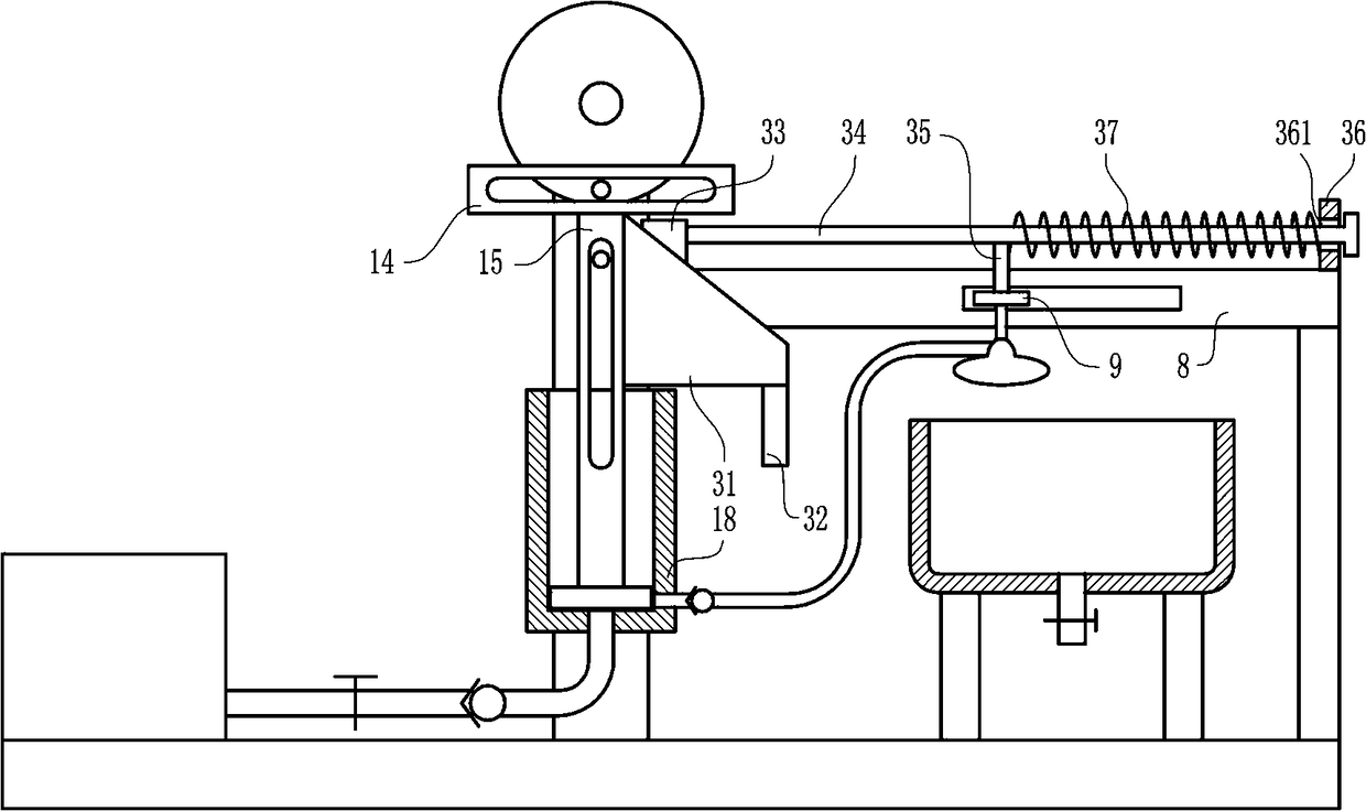
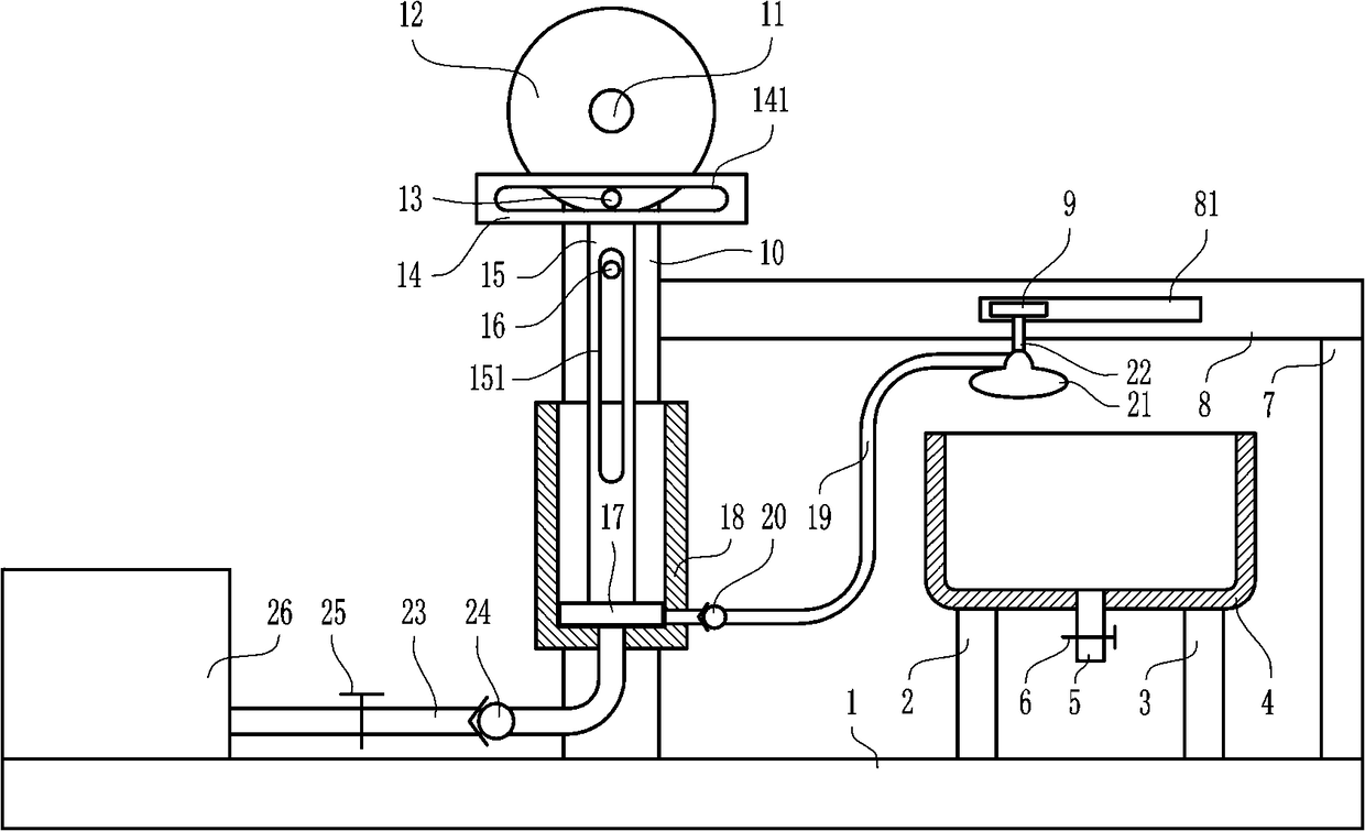
[0027] An oil spray anti-rust device for mechanical parts, such as Figure 1-5 As shown, it includes a base 1, a first leg 2, a second leg 3, a first cylinder body 4, a discharge pipe 5, a first valve 6, a large bracket 7, a top plate 8, a slide plate 9, and a large support plate 10 , large rotating shaft 11, large rotating disk 12, first pin rod 13, lifting plate 14, long connecting plate 15, second pin rod 16, booster plate 17, second cylinder body 18, hose 19, first unit Directional valve 20, spray nozzle 21, small connecting rod 22, connecting pipe 23, second one-way valve 24, second valve 25 and third cylinder body 26, the top of base 1 is connected with first leg 2 and second leg 3. The second leg 3 is located on the right side of the first leg 2, the first cylinder 4 is located above the first leg 2 and the second leg 3, and both the first leg 2 and the second leg 3 are connected to The first cylinder body 4 is connected, and the bottom of the first cylinder body 4 is ...

Embodiment 2

[0029] An oil spray anti-rust device for mechanical parts, such as Figure 1-5 As shown, it includes a base 1, a first leg 2, a second leg 3, a first cylinder body 4, a discharge pipe 5, a first valve 6, a large bracket 7, a top plate 8, a slide plate 9, and a large support plate 10 , large rotating shaft 11, large rotating disk 12, first pin rod 13, lifting plate 14, long connecting plate 15, second pin rod 16, booster plate 17, second cylinder body 18, hose 19, first unit Directional valve 20, spray nozzle 21, small connecting rod 22, connecting pipe 23, second one-way valve 24, second valve 25 and third cylinder body 26, the top of base 1 is connected with first leg 2 and second leg 3. The second leg 3 is located on the right side of the first leg 2, the first cylinder 4 is located above the first leg 2 and the second leg 3, and both the first leg 2 and the second leg 3 are connected to The first cylinder body 4 is connected, and the bottom of the first cylinder body 4 is ...

Embodiment 3

[0032] An oil spray anti-rust device for mechanical parts, such as Figure 1-5 As shown, it includes a base 1, a first leg 2, a second leg 3, a first cylinder body 4, a discharge pipe 5, a first valve 6, a large bracket 7, a top plate 8, a slide plate 9, and a large support plate 10 , large rotating shaft 11, large rotating disk 12, first pin rod 13, lifting plate 14, long connecting plate 15, second pin rod 16, booster plate 17, second cylinder body 18, hose 19, first unit Directional valve 20, spray nozzle 21, small connecting rod 22, connecting pipe 23, second one-way valve 24, second valve 25 and third cylinder body 26, the top of base 1 is connected with first leg 2 and second leg 3. The second leg 3 is located on the right side of the first leg 2, the first cylinder 4 is located above the first leg 2 and the second leg 3, and both the first leg 2 and the second leg 3 are connected to The first cylinder body 4 is connected, and the bottom of the first cylinder body 4 is ...


PUM


Abstract

The invention relates to an oil-injection rust-preventing device for machinery, and particularly relates to an oil-injection rust-preventing device for mechanical parts. The technical problem to be solved by the invention is to provide the oil-injection rust-preventing device for mechanical parts, which is low in labor intensity, time-saving, labor-saving, and thorough in rust prevention, and canprevent a worker's body from being contaminated with oil. In order to solve the technical problem, the invention provides the oil-injection rust-preventing device for mechanical parts. The oil-injection rust-preventing device for mechanical parts comprises a base, a first landing leg, a second landing leg, a first cylinder body, a drain pipe, a first valve, a large bracket, a top plate, a slidingplate, a large support plate, a large rotating shaft and the like; the top of the base is connected with the first landing leg and the second landing leg; and the second landing leg is located at theright side of the first landing leg. The oil-injection rust-preventing device for mechanical parts is low in labor intensity, time-saving, labor-saving, thorough in oil injection and rust prevention,good in rust resistance, clean, and hygienic, can prevent the worker's body from being contaminated with oil, and is safe and reliable in performance.

Description

technical field [0001] The invention relates to an antirust device for machinery, in particular to an oil spray antirust device for mechanical parts. Background technique [0002] Machinery refers to the general term for machines and mechanisms. Machinery is a tool device that can help people reduce the difficulty of work and save labor. Items such as chopsticks, brooms, and tweezers can all be called machinery. They are simple machines, while complex machines are Composed of two or more simple machines, these more complex machines are usually called machines. From the point of view of structure and movement, there is no difference between mechanisms and machines. They are generally called machines. Mechanical gears originally refer to "clever design". ", as a general concept of machinery, can be traced back to the ancient Roman period, mainly to distinguish it from hand tools. The word "machinery" in modern Chinese is the general term for mechanisms and machines. Machinery ...

Claims


Application Information

Patent Timeline
IPC IPC(8): B05B9/00B05B13/02B05B13/04B05B14/00
CPCB05B9/00B05B13/0278B05B13/041B05B14/00
Inventor 何位桥
Owner 何位桥
Why Eureka
Try Eureka