Al technical title is built by PatSnap Al team. It summarizes the technical point description of the patent document.
A stability and joint technology, applied in the field of robotics and engineering bionics, can solve the problems of easy wear, high volatility and poor stability of rigid articulated joints, and achieve the effects of enhancing stability, reducing pressure and reducing contact area.
Active Publication Date: 2021-01-15
JILIN UNIV
View PDF7 Cites 0 Cited by
Summary
Abstract
Description
Claims
Application Information
AI Technical Summary
This helps you quickly interpret patents by identifying the three key elements:
Problems solved by technology
Method used
Benefits of technology
Problems solved by technology
[0006] The purpose of the present invention is to provide an ostrich-like high-speed stable joint to solve the problems of existing rigid hinged joints such as easy wear, rigid impact, excessive extension, poor stability, and high volatility.
Method used
Image
Click on the blue label to locate the original text in one second.
Reading with bidirectional positioning of images and text.
Examples
Embodiment Construction
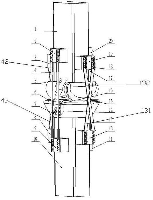
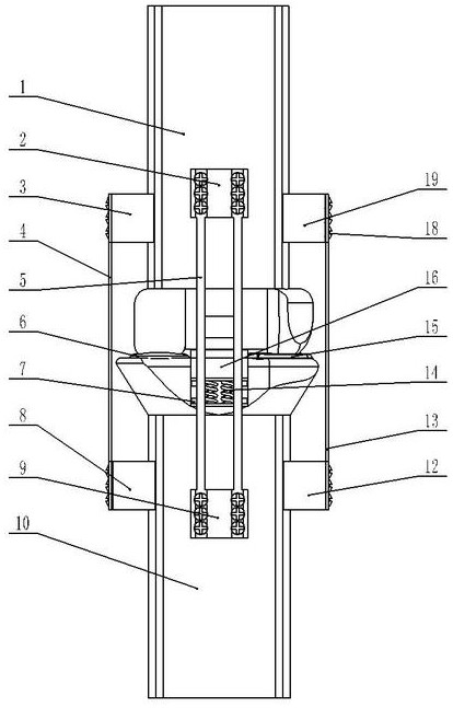
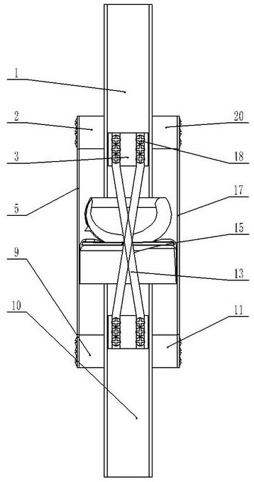
[0030] see Figure 1 to Figure 7 As shown, the far end of the joint and the body of the present invention is the outer side, and the near end is the inner side; a high-speed stability joint imitating an ostrich is composed of a first rigid rod 1, a boss 2 at the upper end of the rear side, and a boss 3 at the upper end of the outer side. , outer cross flexible element 4, rear parallel flexible element 5, outer inter-joint cushion pad 6, socket head cap screw 7, outer lower end boss 8, rear lower end boss 9, second rigid rod 10, front lower end boss Platform 11, inner lower end boss 12, inner cross flexible element 13, double spring buffer seat 14, inner inter-joint buffer pad 15, buffer slider 16, front parallel flexible element 17, pan head screw 18, inner upper end boss 19 It is composed of the boss 20 at the upper end of the front side;
[0031] The outer cross flexible element 4 includes an outer cross outer flexible element 41 and an outer cross inner flexible element 42...
PUM
Abstract
The invention discloses an ostrich-stimulated high-speed stability joint. The joint is composed of a first rigid rod piece, a rear side upper end boss, an outer side upper end boss, an outer side cross flexible element, a rear side parallel flexible element, an outer side joint buffer pad, an inner hexagon screw, an outer side lower end boss, a rear side lower end boss, a second rigid rod piece, afront side lower end boss, an inner side lower end boss, an inner side cross flexible element, a double-spring buffering seat, an inner side inter-joint buffering pad, a buffering sliding block, a front side parallel flexible element, a head screw, an inner side upper end boss and a front side upper end boss. According to the ostrich-stimulated high-speed stability joint, engineering bionic operation is carried out on the special joint morphology, a soft tissue structure as well as a ratchet-similar wheel, a triangular sesamoid bone and other limiting features of an ostrich inter-tarsal-bonejoint, the bionic joint which can be applied to high-speed motion and has internal and external rotation, buffering, antagonism and other limiting features is designed; and a connection movement pairof the joint is a spherical pair, so that various loads caused by different ground environments can be borne without causing abrasion of the surface of the joint.
Description
technical field [0001] The invention belongs to the field of robots and engineering bionics, and in particular relates to an ostrich-like high-speed stability joint. Background technique [0002] Most of the existing mechanical joints are articulated structures, with only one degree of freedom of sagittal plane rotation. When the robot faces a complex external environment, it will cause all-directional loads on the joints, which will cause different degrees of wear on the joints. In addition, most of the hinged structures are rigidly connected. When the joint moves at high speed, rigid impact will occur. At the same time, when the moment of inertia is large, the problem of excessive extension will also occur. [0003] Ostriches are the fastest running bipeds in the world, with a sprint speed exceeding 70km / h. They live in deserts and wastelands all year round. The intertarsal joint of the ostrich is located in the middle of the leg, without muscle wrapping, and only fascia,...
Claims
Application Information
Patent Timeline
Application Date:The date an application was filed.
Publication Date:The date a patent or application was officially published.
First Publication Date:The earliest publication date of a patent with the same application number.
Issue Date:Publication date of the patent grant document.
PCT Entry Date:The Entry date of PCT National Phase.
Estimated Expiry Date:The statutory expiry date of a patent right according to the Patent Law, and it is the longest term of protection that the patent right can achieve without the termination of the patent right due to other reasons(Term extension factor has been taken into account ).
Invalid Date:Actual expiry date is based on effective date or publication date of legal transaction data of invalid patent.
