
Liquid metal continuum mechanical arm structure

A liquid metal, continuum technology, applied in the directions of manipulators, claw arms, manufacturing tools, etc., can solve the problems that the shape change cannot be well realized, and the strength requirements cannot be met.

Pending Publication Date: 2018-09-14
北京思宇博特科技有限公司
View PDF0 Cites 2 Cited by
  • Summary
  • Abstract
  • Description
  • Claims
  • Application Information

AI Technical Summary

Problems solved by technology

[0004] The purpose of the present invention is to provide a liquid metal continuum mechanical arm structure to solve the technical problems that the continuum robot in the prior art cannot achieve shape change well at room temperature and cannot meet the strength requirements

Method used


Image

  • Liquid metal continuum mechanical arm structure
  • Liquid metal continuum mechanical arm structure

Examples


Embodiment 1

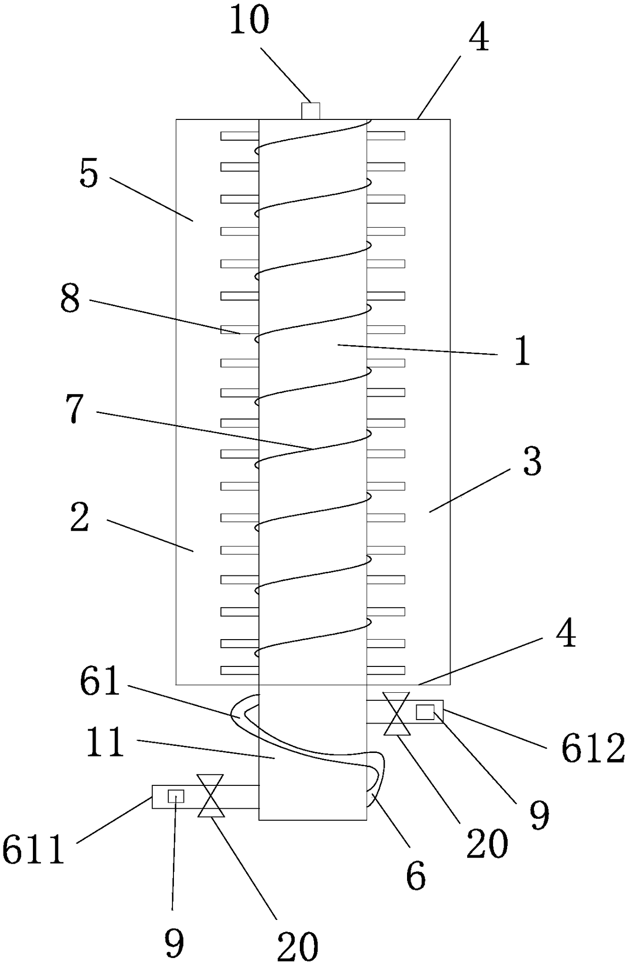
[0025] Such as figure 1 and figure 2 As shown, the figure schematically shows that the liquid metal continuum manipulator structure includes a heat pipe 1 , an outer pipe 2 , an annular space 3 , a sealed end plate 4 , an annular chamber 5 and a heat exchange structure 6 .

[0026] In the embodiment of the present application, the outer pipe 2 is sheathed on the periphery of the heat pipe 1 , and an annular space 3 is formed between the heat pipe 1 and the outer pipe 2 . It should be noted that the heat pipe 1 is equivalent to a heat exchange component capable of heat transfer and temperature reduction.

[0027] The sealing end plates 4 are respectively arranged at both ends of the annular space 3, thereby constructing an annular chamber 5 capable of containing liquid metal, wherein the first end of the heat pipe 1 protrudes between the sealing end plates 4 on the corresponding sides thereof outside. It should be noted that the setting of the sealing end plate 4 can make t...

Embodiment 2

[0033] This embodiment is basically the same as Embodiment 1. For the sake of brevity, in the description process of this embodiment, the same technical features as Embodiment 1 will not be described, and only the differences between this embodiment and Embodiment 1 will be described:

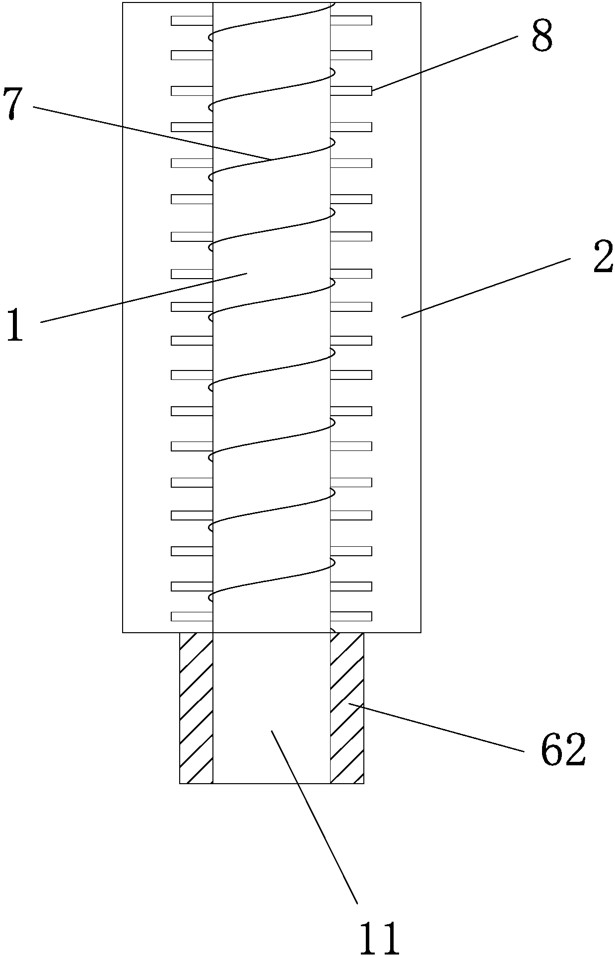
[0034] Such as figure 2 As shown, in another preferred embodiment of the present application, the heat exchange structure 6 is configured to wrap around the first end 11 of the heat pipe 1 ( figure 1Shown lower end) peripheral peltier refrigerating sheet 62. Specifically, the number of the semiconductor cooling fins 62 may be multiple, and the plurality of semiconductor cooling fins 62 are sequentially connected to form a similar ring structure and sleeved around the periphery of the first end 11 of the heat pipe 1 . Among them, the Peltier effect of semiconductor materials is used (Peltier effect refers to that when a current passes through a circuit composed of different conductors, in addi...


PUM


Abstract

The invention relates to the technical field of manufacturing of liquid metal mechanical structures and discloses a liquid metal continuum mechanical arm structure. The liquid metal continuum mechanical arm structure comprises a heat pipe, an outer pipe, sealing end plates and a heat exchange structure. The periphery of the heat pipe is sleeved with the outer pipe, and an annular space is constructed between the heat pipe and the outer pipe. The sealing end plates are arranged at the two ends of the annular space correspondingly, and accordingly an annular cavity capable of containing liquid metal is constructed. The first end of the heat pipe stretches out of the sealing end plate located on the corresponding side of the heat pipe. The heat exchange structure is arranged on the peripheryof the first end of the heat pipe and can heat and cool the heat pipe. The liquid metal continuum mechanical arm structure has the advantages of easy control, uniform heating and short cooling time.

Description

technical field [0001] The invention relates to the technical field of liquid metal mechanical structure manufacturing, in particular to a liquid metal continuum mechanical arm structure. Background technique [0002] The research on continuum robots has just started. Among them, some continuum robots rely on the elasticity of the material itself to deform, but the deformation range of this deformation dependent on the material itself is relatively limited, and some structures will seriously damage its strength. In addition, the continuum robot controlled by means of multi-joint structure, voltage, and air compression has complicated structure and control means, and is not economical. Contents of the invention [0003] (1) Technical problems to be solved [0004] The purpose of the present invention is to provide a liquid metal continuum mechanical arm structure to solve the technical problems that the continuum robot in the prior art cannot realize shape change well at r...

Claims


Application Information

Patent Timeline
IPC IPC(8): B25J18/06
CPCB25J18/06
Inventor 赵清
Owner 北京思宇博特科技有限公司
Learn More