Split type clutch brake

A brake and split technology, applied in manufacturing tools, presses, etc., can solve the problems affecting the service life of forging equipment, uneven clutch connection, poor braking effect, etc., to reduce the difficulty of installation and debugging, smooth connection, and reduce vibration. Effect

Active Publication Date: 2018-09-14
浙江卡卡自动化设备有限公司
View PDF5 Cites 2 Cited by
  • Summary
  • Abstract
  • Description
  • Claims
  • Application Information

AI Technical Summary

Problems solved by technology

[0003] The split clutch brake in the prior art is not stable during actual use, and because the braking effect is poor, it is easy to generate a large inertial force. During the start-up stage of the forging equipment, the forging equipment is started due to the uneven connection of the clutch. Occasionally, a larger one will be used, which will affect the service life of the forging equipment

Method used


Image

  • Split type clutch brake
  • Split type clutch brake
  • Split type clutch brake

Examples


Embodiment 1

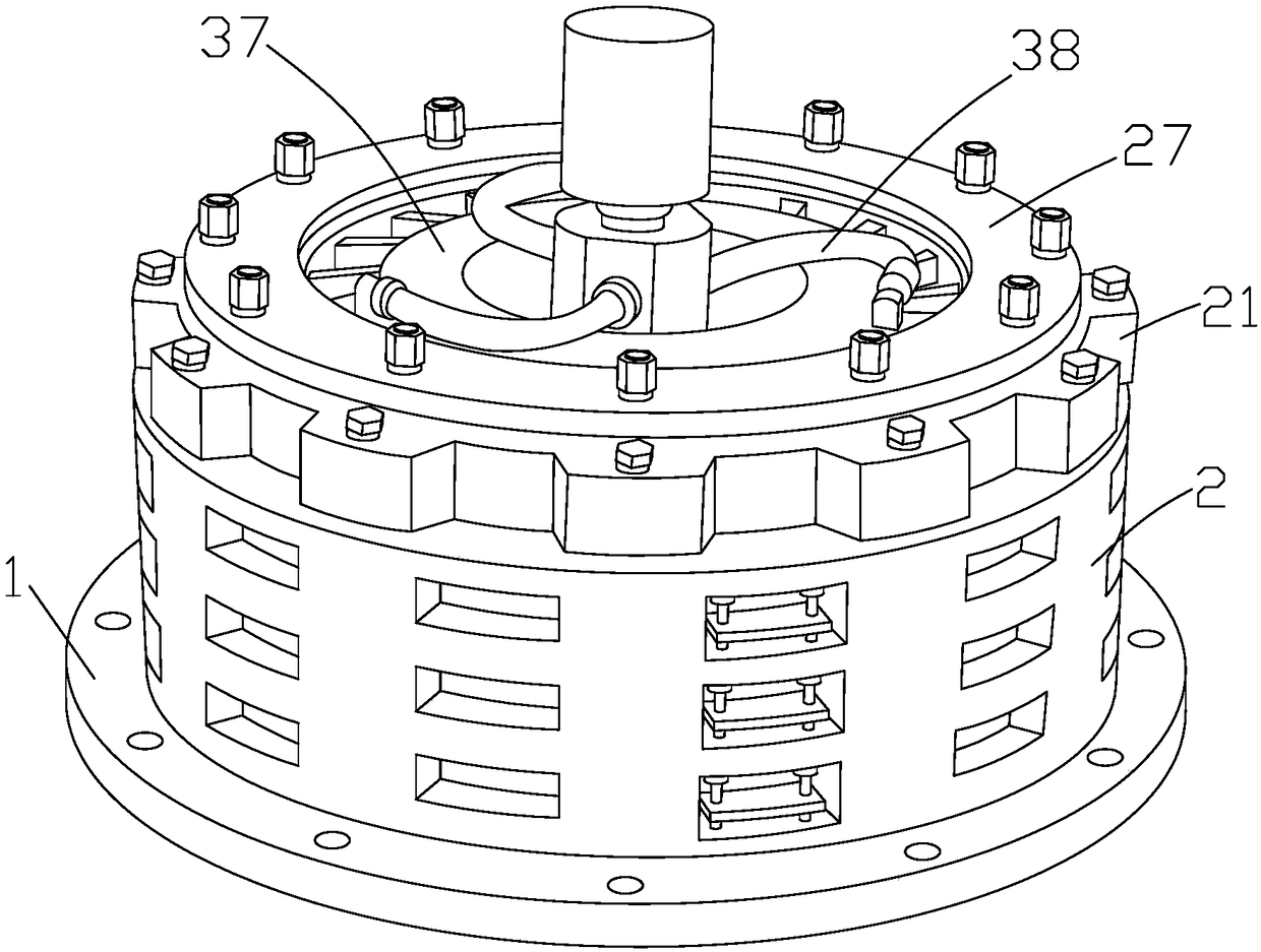
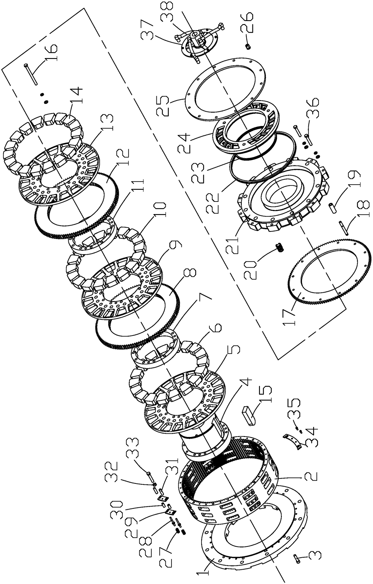
[0027] like Figure 1 to Figure 3 As shown, the split clutch brake of the present invention includes a brake 48 and a clutch 47. The brake 48 is connected to the bed through a positioning ring, the clutch 47 is connected to the flywheel, and the clutch 47 is connected to the brake 48 through the transmission shaft and the air circuit control system. The brake 48 and clutch 47 all include chassis 1, body gear 2, shaft hub 4, first friction assembly, second friction assembly, third friction assembly, cylinder assembly and air intake disc 37, chassis 1 is connected to the body by chassis screws and spring washers 3 Gear 2, the body gear 2 is provided with a spacer 34, the spacer 34 is connected to the body gear 2 through a set screw 35, the shaft hub 4 is located inside the body gear 2, and the side of the shaft hub 4 close to the chassis 1 goes outward in turn The first friction assembly, the second friction assembly and the third friction assembly are sleeved, and the first fri...

Embodiment 2

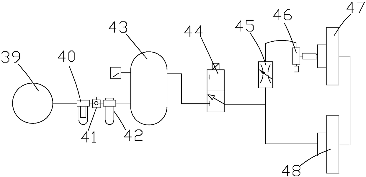
[0036] like figure 1 , figure 2 and Figure 4 As shown, the split clutch brake of the present invention includes a brake 48 and a clutch 47. The brake 48 is connected to the bed through a positioning ring, the clutch 47 is connected to the flywheel, and the clutch 47 is connected to the brake 48 through the transmission shaft and the air circuit control system. The brake 48 and clutch 47 all include chassis 1, body gear 2, shaft hub 4, first friction assembly, second friction assembly, third friction assembly, cylinder assembly and air intake disc 37, chassis 1 is connected to the body by chassis screws and spring washers 3 Gear 2, the body gear 2 is provided with a spacer 34, the spacer 34 is connected to the body gear 2 through a set screw 35, the shaft hub 4 is located inside the body gear 2, and the side of the shaft hub 4 close to the chassis 1 goes outward in turn The first friction assembly, the second friction assembly and the third friction assembly are sleeved, an...


PUM


Abstract

The invention discloses a split type clutch brake. The split type clutch brake comprises a brake and a clutch, wherein the clutch is connected to the brake through a transmission shaft and an air pathcontrol system; the brake and the clutch both comprise a base plate, a machine body gear, a shaft hub, a first friction assembly, a second friction assembly, a third friction assembly, an air cylinder assembly and an air inlet plate; one side, close to the base plate, of the shaft hub is sequentially sleeved with the first friction assembly, the second friction assembly and the third friction assembly; and the third friction assembly is connected to the air cylinder assembly through a movable gear, and the air inlet plate is connected to the air cylinder assembly through a nut, a gasket and aspring. According to the split type clutch brake, the structure is simple, stability and reliability of the split type clutch brake during braking are improved, and inertia force is greatly reduced;the stability of a mechanical device during starting is improved, the running speed of the device at different stages can be smoothly jointed, and the abrasion caused by the transmission mechanism isreduced; and mutual interference between the brake and the clutch is prevented, the installation and debugging difficulty of the device is lowered, and the operation is convenient and flexible.

Description

technical field [0001] The invention relates to a split clutch brake. Background technique [0002] Large-scale forging equipment is mainly used for stamping processes, such as sheet blanking, drawing forming, hot and cold extrusion, etc. The clutch and brake are the key components of the whole forging equipment. Its main function is to realize the fast combination or disconnection of the energy part and the driven part of the main transmission system, and to make the driven part Brake quickly, so as to control the production rhythm and ensure the safety of people and equipment. The clutch and brake control the movement or stop of the forging equipment when the motor and flywheel are constantly rotating, which is also to prevent accidents, improve quality and It is an important part of productivity, so its performance directly affects the working efficiency and production capacity of forging equipment. [0003] The split clutch brake in the prior art is not stable in actua...

Claims


Application Information

Patent Timeline
Patent Type & Authority Applications(China)
IPC IPC(8): B30B15/10B30B15/12
CPCB30B15/10B30B15/12
Inventor 姚学刚邱琪永商豪杰唐鹏尧
Owner 浙江卡卡自动化设备有限公司
Why Eureka
Try Eureka