Skeleton structure of a tensioned expandable space capsule segment

A skeleton structure and space capsule technology, applied in the field of manned spaceflight, can solve problems such as difficult expansion and carrying, and large structural quality, and achieve the effects of mature processing technology, high material utilization rate, and strong scalability

Active Publication Date: 2021-03-23
HARBIN INST OF TECH
View PDF6 Cites 0 Cited by
  • Summary
  • Abstract
  • Description
  • Claims
  • Application Information

AI Technical Summary

Problems solved by technology

[0004] The purpose of the present invention is to solve the problem that the existing space capsule has a large structural mass and is difficult to expand and carry, and to provide a tension-type expandable space capsule skeleton structure

Method used


Image

  • Skeleton structure of a tensioned expandable space capsule segment
  • Skeleton structure of a tensioned expandable space capsule segment
  • Skeleton structure of a tensioned expandable space capsule segment

Examples


specific Embodiment approach 1

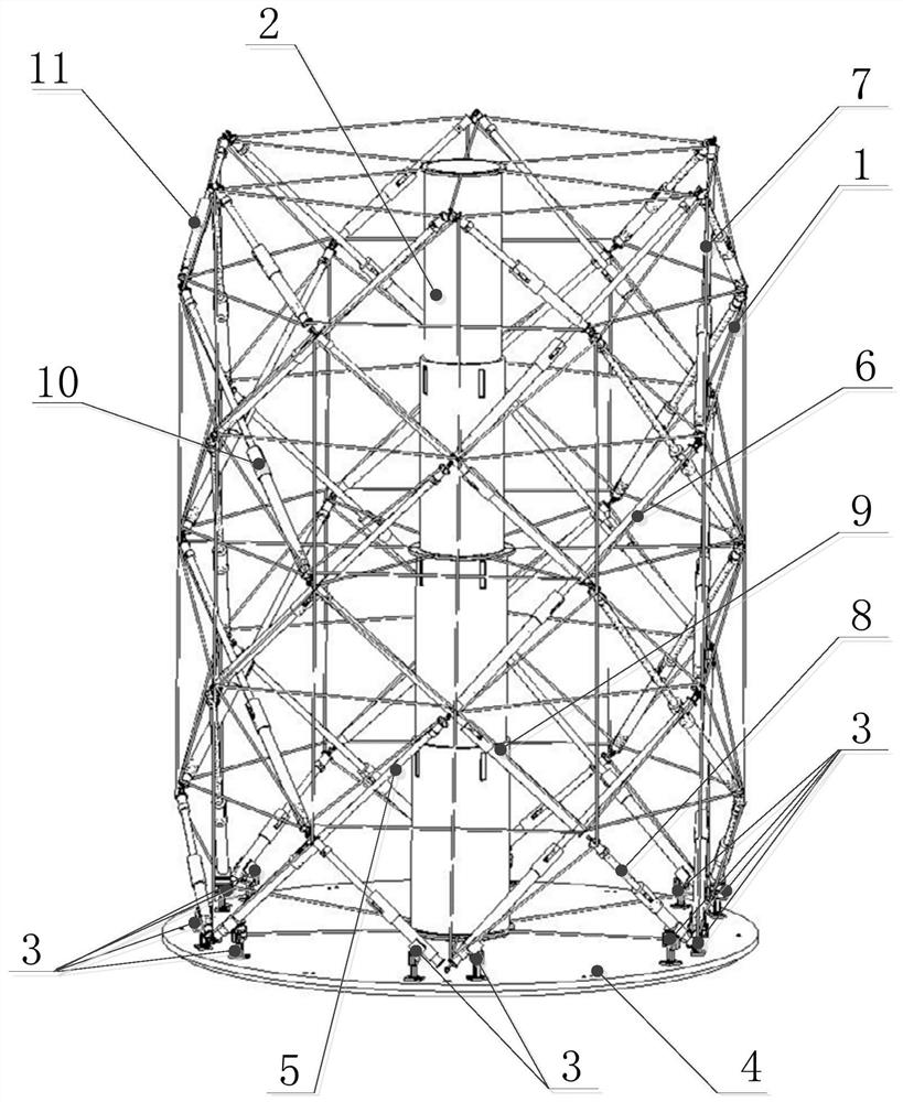
[0033] Specific implementation mode one: combine figure 1 , image 3 and Figure 4 Describe this embodiment, a tension-type expandable space capsule segment skeleton structure of this embodiment, which includes a tension overall frame structure 1, a central retractable core mechanism 2, multiple pairs of connecting frames 3 and a base 4,

[0034]The base 4 is a circular base, the central telescopic core mechanism 2 is vertically arranged at the center of the base 4, the tensegrity frame structure 1 is set on the central telescopic core mechanism 2, and multiple pairs of connecting frames 3 are evenly arranged on the base 4 Above, the tensegrity frame structure 1 is connected to the base 4 through a plurality of pairs of connecting frames 3, the axis of the tensioner frame structure 1 coincides with the axis of the central telescopic stem mechanism 2, and the tensioner frame structure 1 is composed of several The rods and several ropes form a cylindrical net-like telescopic s...

specific Embodiment approach 2

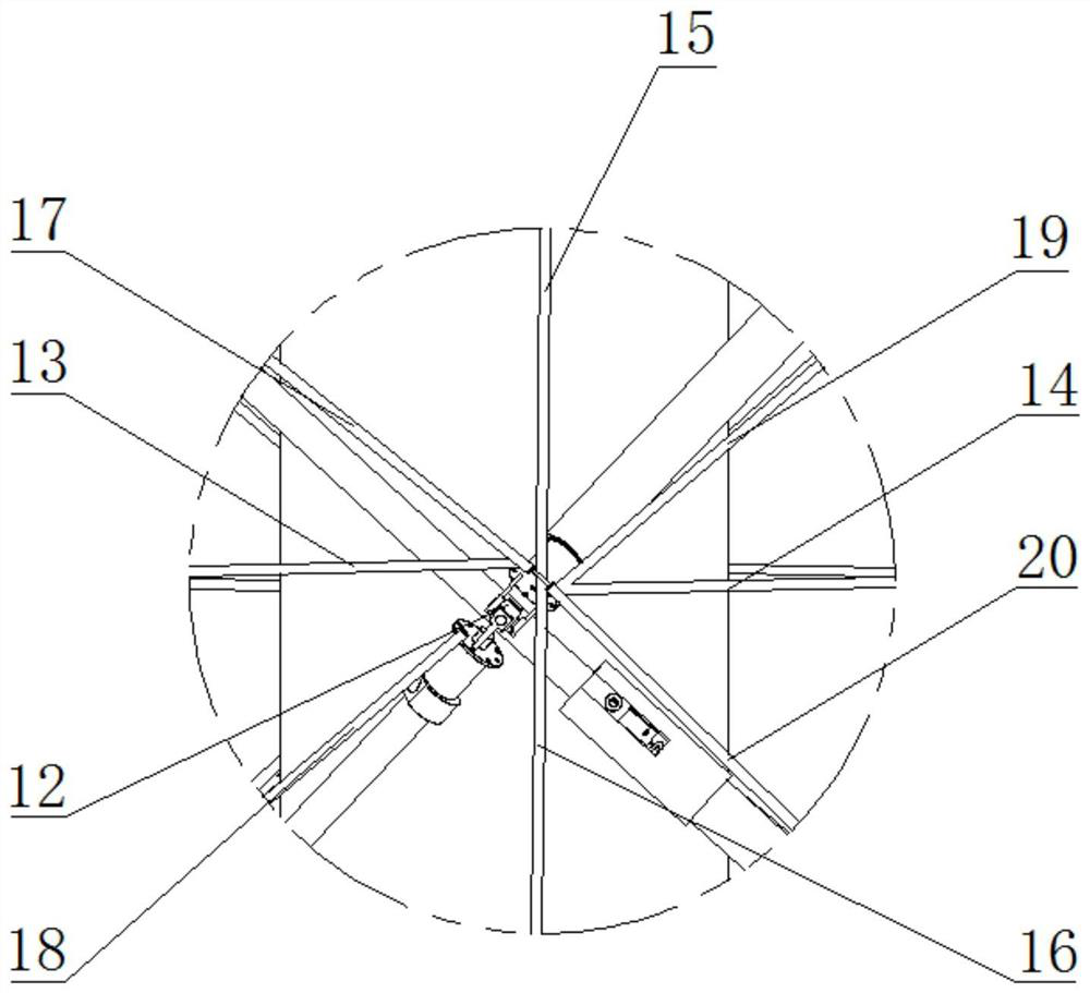
[0035] Specific implementation mode two: combination figure 2 and image 3 To illustrate this embodiment, there is a node between two adjacent rods in the tensegrity frame structure 1 of this embodiment, and a universal joint 12 is arranged at each node, and a universal joint 12 is arranged between two adjacent rods. Connected to the joints 12, the nodes of the tensegrity frame structure 1 are distributed at different levels, from bottom to top are the first layer node unit 21, the second layer node unit 22...the Nth layer node unit, two adjacent Layer node units are equally spaced in the vertical direction, and multiple nodes in each layer node unit are evenly distributed on the same circle. In this way, a universal joint 12 is arranged at each node, so that any angle can be formed between the two connected rods. Other compositions and connections are the same as in the first embodiment.

specific Embodiment approach 3

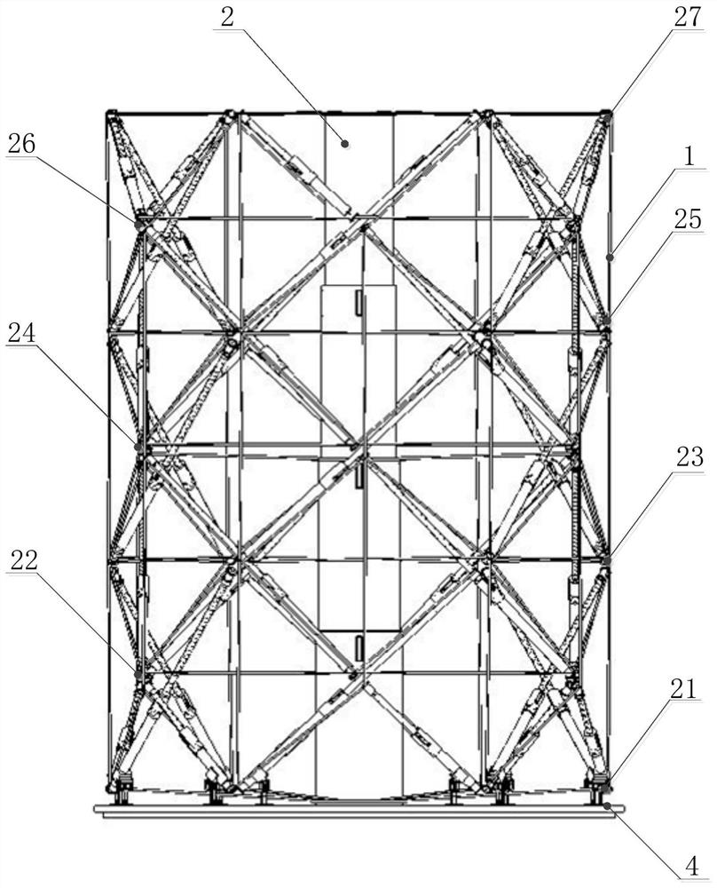
[0036] Specific implementation mode three: combination figure 1 and figure 2 To illustrate this embodiment, there are 42 nodes in the tensegrity frame structure 1 of this embodiment, and the nodes of the tensegrity frame structure 1 are distributed on 7 different levels, and from bottom to top are the first layer of node units 21 , the second layer node unit 22, the third layer node unit 23, the fourth layer node unit 24, the fifth layer node unit 25, the sixth layer node unit 26 and the seventh layer node unit 27, in each layer node unit The six nodes are evenly distributed on the same circle, and the central angle corresponding to the adjacent nodes is 60°;

[0037] The rods of the tensegrity frame structure 1 include multiple long rods and multiple short rods with the same structure and different lengths. Starting from a node in the node unit 21 of the first layer, the three long rods are inclined counterclockwise upward along the circumferential direction. Arrangement, ...


PUM


Abstract

The invention discloses a stretch-draw type expansible space capsule section skeleton structure, and relates to the field of manned space flight. The problems that an existing space capsule section islarge in structure mass and hard to expand or convey are solved. A base is a circular base, a central stretchable core column mechanism is perpendicularly arranged in the center of the base, the central stretchable core column mechanism is sleeved with a whole stretch-draw frame structure, multiple pairs of connecting frames are evenly arranged on the base, the whole stretch-draw frame structureis connected with the base through multiple pair of connecting frames, the axis of the whole stretch-draw frame structure coincides with the axis of the central stretchable core column mechanism, andthe whole stretch-draw frame structure is a net-shaped stretchable structure composed of a plurality of rod pieces and a plurality of ropes, wherein the appearance of the net-shaped stretchable structure is cylindrical; the rod pieces of the whole stretch-draw frame structure are all stretchable rod pieces, the whole frame can be expanded by means of stretching and retracting of the rod pieces, and meanwhile, the central stretchable core column mechanism is expanded under the drive of external force. The stretch-draw type expansible space capsule section skeleton structure is high in expansibility and the folding space is normal.

Description

technical field [0001] The invention relates to the field of manned spaceflight, in particular to a skeleton structure of a tensioned expandable space capsule segment. Background technique [0002] With the development of manned spaceflight technology, humans will build a new generation of space stations and bases on the moon and Mars in the future, and carry out conceptual design research on the livable environment and facilities for future manned space exploration. Introducing the design concept of ergonomics and modular foldable electromechanical system, designing a lightweight and expandable cabin that meets the needs of future manned detection has become an urgent problem to be overcome. Although the currently applied cabin structure can provide astronauts with a livable environment in space, it includes a large number of rigid components, which not only increases the mass of the structure, but is also difficult to expand and carry, which has become a bottleneck for the...

Claims


Application Information

Patent Timeline
Patent Type & Authority Patents(China)
IPC IPC(8): B64G1/12B64G1/60
CPCB64G1/12B64G1/60
Inventor 郭宏伟刘荣强邓宗全耿金嵩田志东
Owner HARBIN INST OF TECH
Why Eureka
Try Eureka