
Textile wool removal device

A textile fabric and wool sticking technology, which is applied in the field of textile hair removal devices, can solve the problems of unsatisfactory hair removal effect and inability to improve the overall quality of textile fabrics, and achieve the effects of increasing quality, reducing loss, and improving hair removal efficiency

Inactive Publication Date: 2018-09-14
PINGHU YIFANJIA LUGGAGE CO LTD
View PDF0 Cites 10 Cited by
  • Summary
  • Abstract
  • Description
  • Claims
  • Application Information

AI Technical Summary

Problems solved by technology

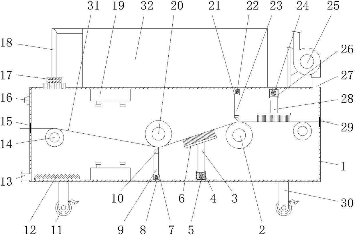
[0002] The original meaning of textile is taken from the general term of spinning and weaving, but with the continuous development and improvement of the textile knowledge system and subject system, especially after the emergence of non-woven textile materials and three-dimensional composite weaving technologies, the current textile is not only a traditional Hand spinning and weaving also include non-woven fabric technology, modern three-dimensional weaving technology, modern electrostatic nano-netting technology, etc. Therefore, modern textile refers to a multi-scale structure processing technology of fibers or fiber aggregates. Ancient Chinese Textile and printing and dyeing technology has a very long history. As early as the primitive society, in order to adapt to climate change, the ancients knew how to obtain local materials, use natural resources as raw materials for textile and printing and dyeing, and manufacture simple hand-made textile tools. Until today, Our daily clothes, some daily necessities and works of art are all products of weaving and printing and dyeing technology. Since the textile fabrics will produce fluff during the production process, it needs to be depilated. However, the existing depilatory devices The hair removal effect is not ideal, and the overall quality of the textile fabric cannot be improved. Therefore, we propose a hair removal device for textile use

Method used

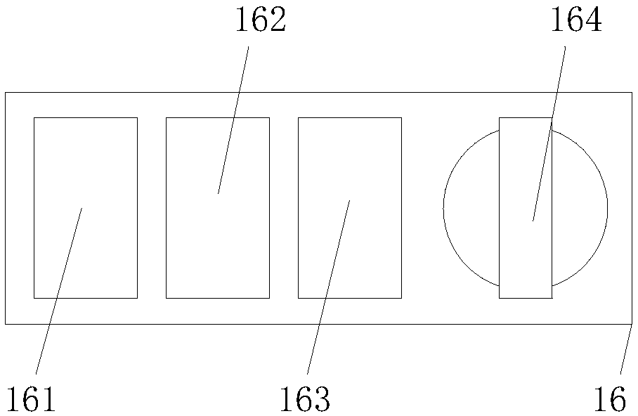
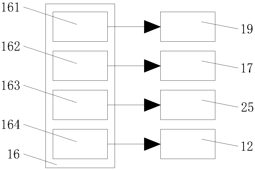

Image

  • Textile wool removal device
  • Textile wool removal device
  • Textile wool removal device

Examples


Embodiment Construction

[0022] The following will clearly and completely describe the technical solutions in the embodiments of the present invention with reference to the accompanying drawings in the embodiments of the present invention. Obviously, the described embodiments are only some, not all, embodiments of the present invention. Based on the embodiments of the present invention, all other embodiments obtained by persons of ordinary skill in the art without making creative efforts belong to the protection scope of the present invention.

[0023] see Figure 1-3 , a hair removal device for textiles, comprising a housing 1, the left and right ends of the inner cavity of the housing 1 are movably installed with conveying rollers 14, and the inner cavity of the housing 1 is movably installed at the right end of the left conveying roller 14. A sticking roller 20, the inner cavity of the housing 1 and the left end of the right delivery roller 14 are movably installed with the second sticking roller 2...


PUM


Abstract

The invention discloses a textile wool removal device which comprises a shell. Conveying rollers are movably mounted at the left end and the right end of an inner cavity of the shell, a first wool sticking roller is movably mounted in the inner cavity of the shell and positioned at the right end of the left conveying roller, a second wool sticking roller is movably mounted in the inner cavity of the shell and positioned a the left end of the right conveying roller, the second wool sticking roller, the first wool sticking roller and the two conveying rollers are in transmission connection through textile fabrics, electrostatic generators are symmetrically arranged at the left ends of the top and the bottom of the inner cavity of the shell, and a heating wire is fixedly connected at the bottom of the inner cavity of the shell and positioned at the left end of the bottom electrostatic generator. Wool flocculi on the upper surface and the lower surface of a textile fabric can be efficiently removed under actions of the electrostatic generators, the first wool sticking roller, the second wool sticking roller, electrostatic brushes and electrostatic scrapers, the wool removal efficiencyof the device is improved, the quality of the textile fabric is improved, and the device meets enterprise benefits.

Description

technical field [0001] The invention relates to the technical field of textile equipment, in particular to a hair removal device for textile. Background technique [0002] The original meaning of textile is taken from the general term of spinning and weaving, but with the continuous development and improvement of the textile knowledge system and subject system, especially after the emergence of non-woven textile materials and three-dimensional composite weaving technologies, the current textile is not only a traditional Hand spinning and weaving also include non-woven fabric technology, modern three-dimensional weaving technology, modern electrostatic nano-netting technology, etc. Therefore, modern textile refers to a multi-scale structure processing technology of fibers or fiber aggregates. Ancient Chinese Textile and printing and dyeing technology has a very long history. As early as the primitive society, in order to adapt to climate change, the ancients knew how to obtai...

Claims


Application Information

Patent Timeline
IPC IPC(8): D06C13/00
CPCD06C13/00
Inventor 韩祥
Owner PINGHU YIFANJIA LUGGAGE CO LTD
Learn More