Opposed power generation module, and unmanned aerial vehicle containing opposed power generation module

A power generation module, opposing technology, applied in the direction of engine components, power plant types, machines/engines, etc., can solve the problems of reducing the size and weight of the power generation module, unable to realize variable transmission ratio transmission, and supporting parts with large forces. , to achieve the effect of compact structure, stable and reliable flight, and small force on parts

Pending Publication Date: 2018-09-14
HUAZHONG UNIV OF SCI & TECH +1
View PDF5 Cites 3 Cited by
  • Summary
  • Abstract
  • Description
  • Claims
  • Application Information

AI Technical Summary

Problems solved by technology

However, the direct connection of the engine to the generator cannot achieve variable transmission ratio transmission, and the way that a transmission system drives a single motor to generate electricity generally requires a large installation space, and it will give a large final force to the drive shaft, and at the same time, the supporting parts are affected. The force will also be large, which is not conducive to reducing the size and weight of the power generation module

Method used


Image

  • Opposed power generation module, and unmanned aerial vehicle containing opposed power generation module
  • Opposed power generation module, and unmanned aerial vehicle containing opposed power generation module
  • Opposed power generation module, and unmanned aerial vehicle containing opposed power generation module

Examples


Embodiment Construction

[0044] In order to make the object, technical solution and advantages of the present invention clearer, the present invention will be further described in detail below in conjunction with the accompanying drawings and embodiments. It should be understood that the specific embodiments described here are only used to explain the present invention, not to limit the present invention. In addition, the technical features involved in the various embodiments of the present invention described below can be combined with each other as long as they do not constitute a conflict with each other.

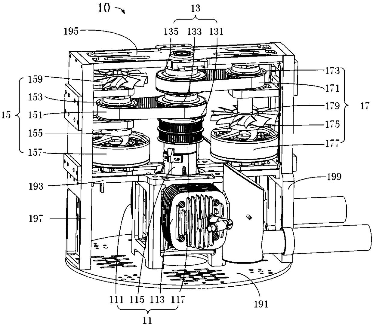
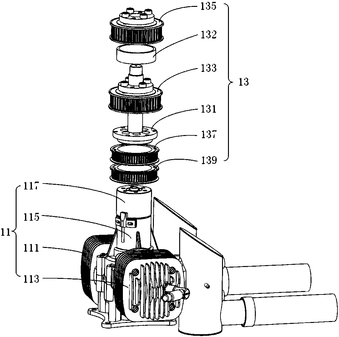
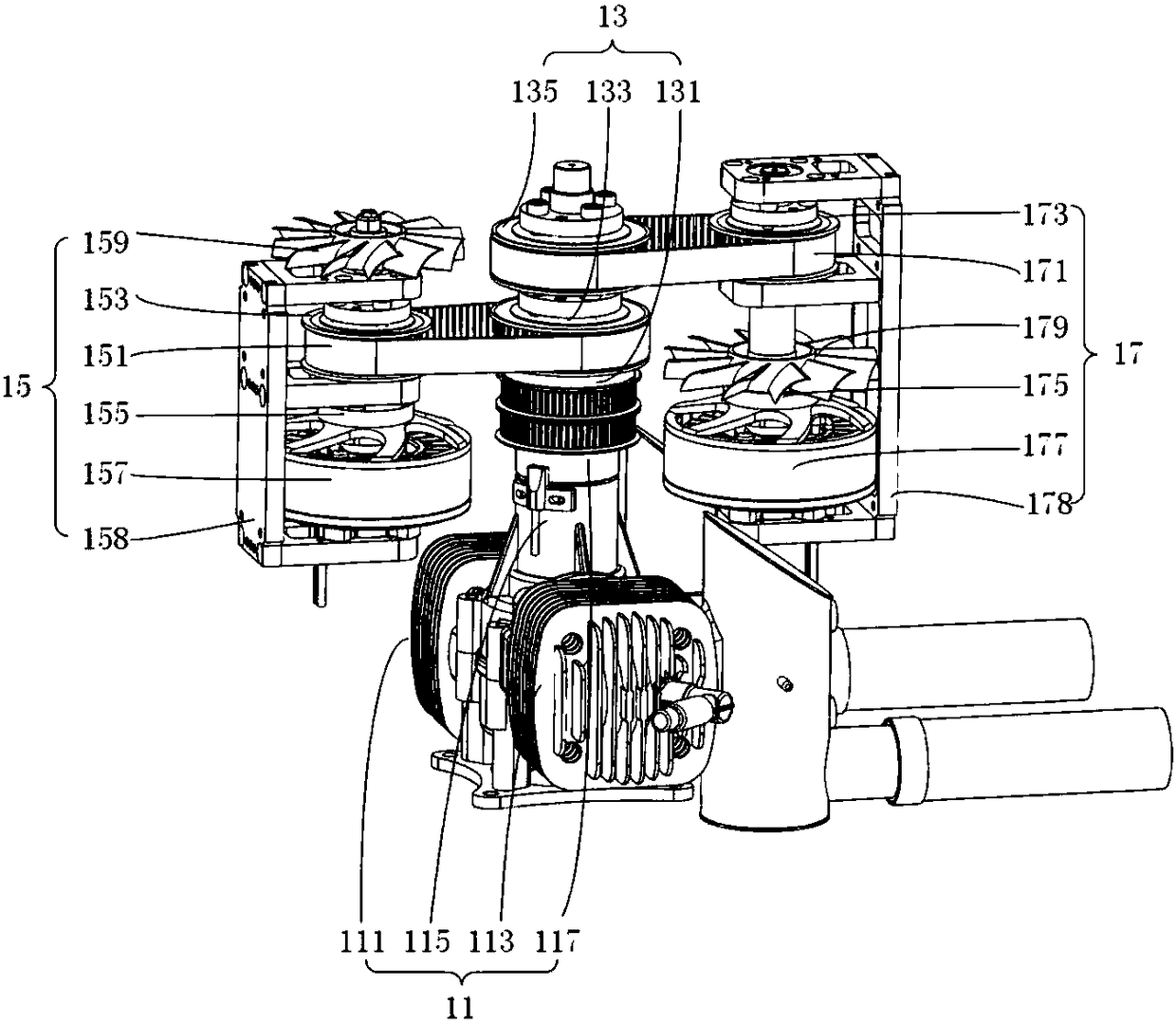
[0045] refer to Figure 1 to Figure 8 , an opposed power generation module 10, including an engine assembly 11, a driving shaft assembly 13, and a generator assembly, wherein,

[0046] Described engine assembly 11 comprises cylinder support, cylinder, crankcase 115 and engine output shaft 117, and described cylinder support is installed on the first horizontal support plate 191, and described c...


PUM


Abstract

The invention belongs to the field of unmanned aerial vehicles, and discloses an opposed power generation module which comprises an engine assembly, a driving shaft assembly and power generator assemblies. The engine assembly comprises an air cylinder support, air cylinders, a crankcase and an engine output shaft; the two air cylinder are arranged on two sides of the crankcase front and back; pistons of the two air cylinders are connected with a crankshaft and connecting rod mechanism in the crankcase; the crankshaft and connecting rod mechanism is connected with the engine output shaft; the driving shaft assembly comprises a driving shaft and a driving wheel; two groups of power generator assemblies are arranged; each group of power generator assembly comprises a power generation support,a power generator, a driven shaft, a driven wheel, a belt and a fan; and the two driven shafts are left-and-right symmetrically arranged on two sides of the driving shaft. The opposed power generation module provided by the invention offsets a pull force of the driving shaft, so that a bending force stressed on the driving shaft is reduced, the structure is compact, and the layout is reasonable;and the unmanned aerial vehicle acquires electric energy through the opposed power generation module so as to have a long flight time.

Description

technical field [0001] The invention belongs to the field of unmanned aerial vehicles, and more specifically relates to an opposed power generation module and an unmanned aerial vehicle including the opposed power generation module. Background technique [0002] In the existing civilian multi-rotor UAVs, most of them use motors to drive the propellers, and provide electric energy for the motors through batteries. Due to the limited energy density of the battery, simply increasing the capacity of the battery will inevitably increase the weight of the battery, thereby increasing the take-off weight of the drone, which in turn requires more power to drive the motor; the increase in battery power consumption will eventually lead to the inability to Significantly increased flight time, or even reduced flight time. In addition, UAVs with more batteries tend to be larger in size and take-off weight, which is not conducive to the miniaturization of UAVs. [0003] Since the energy ...

Claims


Application Information

Patent Timeline
Patent Type & Authority Applications(China)
IPC IPC(8): F02B63/04F02B67/06F02B75/24F01P1/02F01P5/04H02K9/06B64D27/02B64D33/10
CPCH02K9/06F01P1/02F01P5/04F02B63/042F02B63/044F02B67/06F02B75/243B64D27/02B64D33/10F01P2001/023F01P2005/025F02B2075/1808F02B2063/045B64D27/026
Inventor 熊蔡华王博艾永恒何杰
Owner HUAZHONG UNIV OF SCI & TECH
Why Eureka
Try Eureka